CAN COMMUNICATION SYSTEM (for Sedan) > TERMINALS OF ECU |
| JUNCTION CONNECTOR |
![]() |
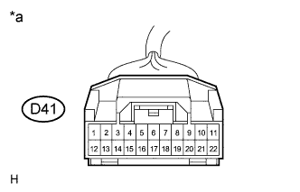
D-CAN Junction Connector
| *a | Front view of wire harness connector (to D-CAN Junction Connector) |
| D-CAN Junction Connector | Terminal No. (Symbol) | Wiring Color |
| Skid Control ECU*1 (CAN-H) | D41-1 (ABS) | G |
| Skid Control ECU*1 (CAN-L) | D41-12 (ABS) | W |
| DLC3 (CAN-H) | D41-3 (OBD) | V |
| DLC3 (CAN-L) | D41-14 (OBD) | W |
| ECM (CAN-H) | D41-4 (EFI) | L |
| ECM (CAN-L) | D41-15 (EFI) | W |
| Air Conditioning Amplifier*2 (CAN-H) | D41-6 (A/C) | V |
| Air Conditioning Amplifier*2 (CAN-L) | D41-17 (A/C) | W |
| Center Airbag Sensor Assembly (CAN-H) | D41-8 (A/B) | B |
| Center Airbag Sensor Assembly (CAN-L) | D41-19 (A/B) | W |
| CAN Main Wire (between D-CAN and P-CAN Junction Connector) | D41-11 (TORH) | Y |
| CAN Main Wire (between D-CAN and P-CAN Junction Connector) | D41-22 (TORH) | W |
| JUNCTION CONNECTOR |
![]() |
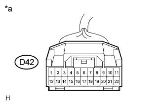
P-CAN Junction Connector
| *a | Front view of wire harness connector (to P-CAN Junction Connector) |
| P-CAN Junction Connector | Terminal No. (Symbol) | Wiring Color |
| Power Steering ECU (CAN-H) | D42-4 (EPS) | SB |
| Power Steering ECU (CAN-L) | D42-15 (EPS) | W |
| Main Body ECU (CAN-H) | D42-5 (JB) | R |
| Main Body ECU (CAN-L) | D42-16 (JB) | W |
| Combination Meter ECU (CAN-H) | D42-7 (MET) | G |
| Combination Meter ECU (CAN-L) | D42-18 (MET) | W |
| CAN Main Wire (between P-CAN and D-CAN Junction Connector) | D42-11 (TOLH) | Y |
| CAN Main Wire (between P-CAN and D-CAN Junction Connector) | D42-22 (TOLH) | W |
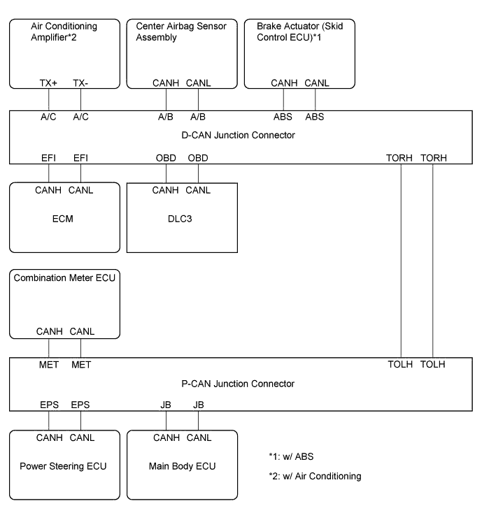
Wiring diagram for identifying CAN junction connectors

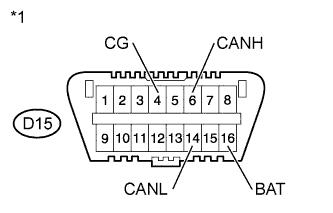
| DLC3 |
![]() |
Turn the ignition switch off.
Measure the resistance according to the value(s) in the table below.
| *1 | DLC3 |
| Terminal No. (Symbol) | Wiring Color | Switch Condition | Specified Condition |
| D15-6 (CANH) - D15-14 (CANL) | V - W | Ignition switch off | 54 to 69 Ω |
| D15-6 (CANH) - D15-4 (CG) | V - W-B | Ignition switch off | 200 Ω or higher |
| D15-14 (CANL) - D15-4 (CG) | W - W-B | Ignition switch off | 200 Ω or higher |
| D15-6 (CANH) - D15-16 (BAT) | V - SB | Ignition switch off | 6 kΩ or higher |
| D15-14 (CANL) - D15-16 (BAT) | W - SB | Ignition switch off | 6 kΩ or higher |
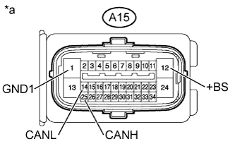
| BRAKE ACTUATOR (SKID CONTROL ECU) (w/ ABS) |
![]() |
Turn the ignition switch off.
Disconnect the A15 brake actuator (skid control ECU) connector.
Measure the resistance according to the value(s) in the table below.
| *a | Front view of wire harness connector (to Brake Actuator (Skid Control ECU)) |
| Terminal No. (Symbol) | Wiring Color | Switch Condition | Specified Condition |
| A15-25 (CANH) - A15-14 (CANL) | G - W | Ignition switch off | 54 to 69 Ω |
| A15-25 (CANH) - A15-1 (GND1) | G - W-B | Ignition switch off | 200 Ω or higher |
| A15-14 (CANL) - A15-1 (GND1) | W - W-B | Ignition switch off | 200 Ω or higher |
| A15-25 (CANH) - A15-12 (+BS) | G - W | Ignition switch off | 6 kΩ or higher |
| A15-14 (CANL) - A15-12 (+BS) | W - W | Ignition switch off | 6 kΩ or higher |
| ECM |
![]() |
Turn the ignition switch off.
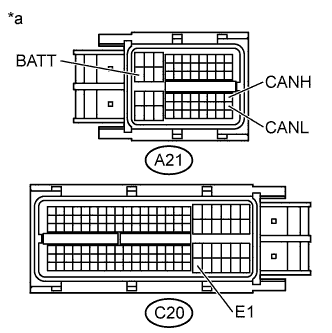
Disconnect the A21 and C20 ECM connectors.
Measure the resistance according to the value(s) in the table below.
| *a | Front view of wire harness connector (to ECM) |
| Terminal No. (Symbol) | Wiring Color | Switch Condition | Specified Condition |
| A21-41 (CANH) - A21-49 (CANL) | L - W | Ignition switch off | 108 to 132 Ω |
| A21-41 (CANH) - C20-104 (E1) | L - W | Ignition switch off | 200 Ω or higher |
| A21-49 (CANL) - C20-104 (E1) | W - W | Ignition switch off | 200 Ω or higher |
| A21-41 (CANH) - A21-20 (BATT) | L - Y | Ignition switch off | 6 kΩ or higher |
| A21-49 (CANL) - A21-20 (BATT) | W - Y | Ignition switch off | 6 kΩ or higher |
| CENTER AIRBAG SENSOR ASSEMBLY |
![]() |
Turn the ignition switch off.
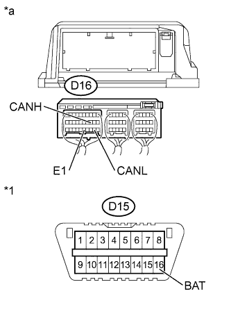
Disconnect the D16 center airbag sensor assembly connector.
Measure the resistance according to the value(s) in the table below.
| *1 | DLC3 |
| *a | Rear view of wire harness connector (to Center Airbag Sensor Assembly) |
| Terminal No. (Symbol) | Wiring Color | Switch Condition | Specified Condition |
| D16-13 (CANH) - D16-22 (CANL) | B - W | Ignition switch off | 54 to 69 Ω |
| D16-13 (CANH) - D16-25 (E1) | B - W-B | Ignition switch off | 200 Ω or higher |
| D16-22 (CANL) - D16-25 (E1) | W - W-B | Ignition switch off | 200 Ω or higher |
| D16-13 (CANH) - D15-16 (BAT) | B - SB | Ignition switch off | 6 kΩ or higher |
| D16-22 (CANL) - D15-16 (BAT) | W - SB | ignition switch off | 6 kΩ or higher |
| AIR CONDITIONING AMPLIFIER (w/ Air Conditioning) |
![]() |
Turn the ignition switch off.
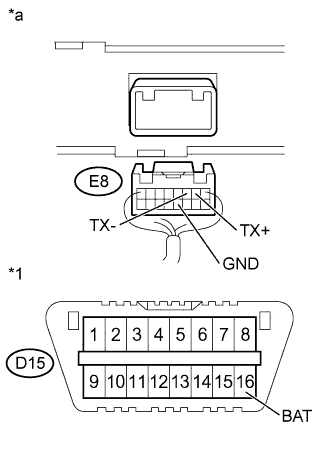
Disconnect the E8 air conditioning amplifier connector.
Measure the resistance according to the value(s) in the table below.
| *1 | DLC3 |
| *a | Rear view of wire harness connector (to Air Conditioning Amplifier) |
| Terminal No. (Symbol) | Wiring Color | Switch Condition | Specified Condition |
| E8-2 (TX+) - E8-3 (TX-) | V - W | Ignition switch off | 54 to 69 Ω |
| E8-2 (TX+) - E8-12 (GND) | V - W-B | Ignition switch off | 200 Ω or higher |
| E8-3 (TX-) - E8-12 (GND) | W - W-B | Ignition switch off | 200 Ω or higher |
| E8-2 (TX+) - D15-16 (BAT) | V - SB | Ignition switch off | 6 kΩ or higher |
| E8-3 (TX-) - D15-16 (BAT) | W - SB | Ignition switch off | 6 kΩ or higher |
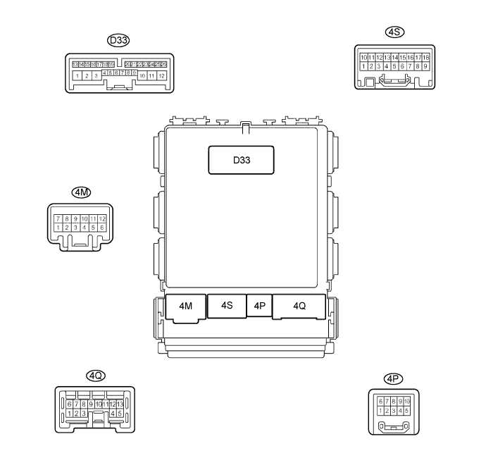
| MAIN BODY ECU |


Turn the ignition switch off.
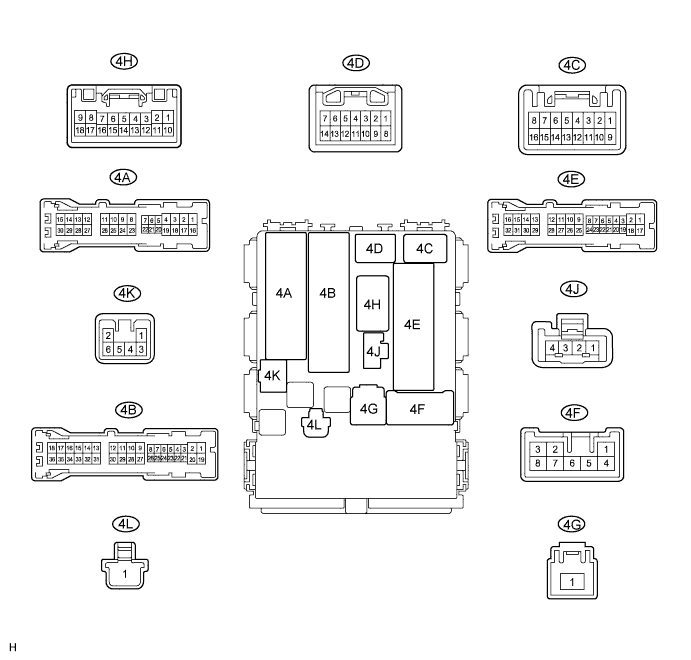
Disconnect the D33, 4B and 4E main body ECU connectors.
Measure the resistance according to the value(s) in the table below.
| Terminal No. (Symbol) | Wiring Color | Switch Condition | Specified Condition |
| D33-23 (CANH) - D33-22 (CANL) | R - W | Ignition switch off | 54 to 69 Ω |
| D33-23 (CANH) - 4E-17 (GND1) | R - W-B | Ignition switch off | 200 Ω or higher |
| D33-22 (CANL) - 4E-17 (GND1) | W - W-B | Ignition switch off | 200 Ω or higher |
| D33-23 (CANH) - 4B-30 (BECU) | R - L | Ignition switch off | 6 kΩ or higher |
| D33-22 (CANL) - 4B-30 (BECU) | W - L | Ignition switch off | 6 kΩ or higher |
| COMBINATION METER ECU |
![]() |
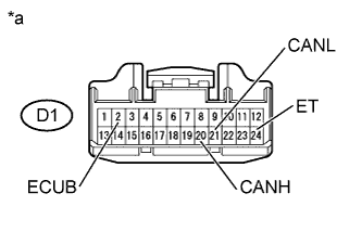
Turn the ignition switch off.
Disconnect the D1 combination meter ECU connector.
Measure the resistance according to the value(s) in the table below.
| *a | Front view of wire harness connector (to Combination Meter ECU) |
| Terminal No. (Symbol) | Wiring Color | Switch Condition | Specified Condition |
| D1-20 (CANH) - D1-21 (CANL) | G - W | Ignition switch off | 54 to 69 Ω |
| D1-20 (CANH) - D1-24 (ET) | G - BR | Ignition switch off | 200 Ω or higher |
| D1-21 (CANL) - D1-24 (ET) | W - BR | Ignition switch off | 200 Ω or higher |
| D1-20 (CANH) - D1-2 (ECUB) | G - L | Ignition switch off | 6 kΩ or higher |
| D1-21 (CANL) - D1-2 (ECUB) | W - L | Ignition switch off | 6 kΩ or higher |
| POWER STEERING ECU |
![]() |
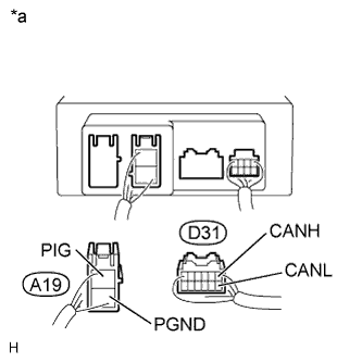
Turn the ignition switch off.
Disconnect the A19 and D31 power steering ECU connectors.
Measure the resistance according to the value(s) in the table below.
| *a | Rear view of wire harness connector (to Power Steering ECU) |
| Terminal No. (Symbol) | Wiring Color | Switch Condition | Specified Condition |
| D31-1 (CANH) - D31-7 (CANL) | SB - W | Ignition switch off | 108 to 132 Ω |
| D31-1 (CANH) - A19-2 (PGND) | SB - W-B | Ignition switch off | 200 Ω or higher |
| D31-7 (CANL) - A19-2 (PGND) | W - W-B | Ignition switch off | 200 Ω or higher |
| D31-1 (CANH) - A19-1 (PIG) | SB - W | Ignition switch off | 6 kΩ or higher |
| D31-7 (CANL) - A19-1 (PIG) | W - W | Ignition switch off | 6 kΩ or higher |