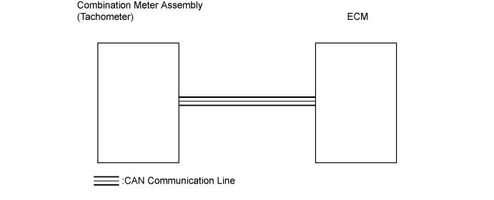
METER / GAUGE SYSTEM (for Sedan) > Tachometer Malfunction |
| 1.PERFORM ACTIVE TEST USING TECHSTREAM (TACHOMETER) |
Connect the Techstream to the DLC3.
Turn the ignition switch ON and turn the tester ON.
Enter the following menus: Body Electrical / Combination Meter /Active Test.
| Tester Display | Test Part | Control Range | Diagnostic Note |
| Tachometer Operation | Tachometer | 0/1000/2000/3000/4000/5000/6000/7000 rpm | - |
|
| ||||
| OK | |
 |
| 2.READ VALUE USING TECHSTREAM (TACHOMETER) |
Connect the Techstream to the DLC3.
Turn the ignition switch ON and turn the tester ON.
Select the item below from the Data List, and read the value displayed on the Techstream.
| Tester Display | Measurement Item/Range | Normal Condition | Diagnostic Note |
| Engine Rpm | Engine speed/Min.: 0 rpm, Max.: 12,750 rpm | Approximately same as actual engine speed (When engine is running) | - |
|
| ||||
| OK | ||
 | ||
| ||
