 |
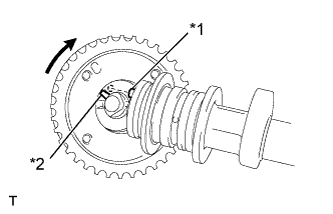
Put the camshaft timing gear assembly and camshaft together with the straight pin of the groove.
| *1 | Straight Pin |
| *2 | Groove |
CAMSHAFT (for Hatchback) > INSTALLATION |
| 1. INSTALL CAMSHAFT TIMING GEAR ASSEMBLY |
|
Put the camshaft timing gear assembly and camshaft together with the straight pin of the groove.
| *1 | Straight Pin |
| *2 | Groove |
Turn the camshaft timing gear assembly clockwise while pushing it gently toward the camshaft. Push further at the position where the pin fits into the groove.
Check that there is no clearance between the gear flange and the camshaft.
Tighten the flange bolt with the camshaft timing gear fixed.
Check that the camshaft timing gear assembly can move to the retard angle (to the right) and is locked in the most retarded position.
| 2. INSTALL CAMSHAFT |
Apply a light coat of engine oil to the camshaft and camshaft journals.
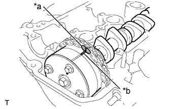 |
Install the chain onto the camshaft timing gear with the paint mark and the timing mark aligned as shown in the illustration.
| *a | Paint Mark |
| *b | Timing Mark |
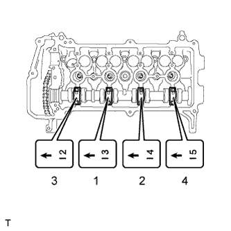 |
Examine the front marks and numbers on the No. 2 camshaft bearing cap and check that the sequence is as shown in the illustration. Then uniformly tighten the bolts, in several steps, in the sequence shown in the illustration.
| 3. INSTALL NO. 2 CAMSHAFT |
Install the No. 2 camshaft.
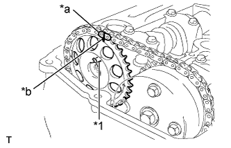 |
Hold the chain and align the timing mark on the camshaft timing sprocket with the paint mark of the chain.
| *1 | Pin |
| *a | Paint Mark |
| *b | Timing Mark |
Align the alignment pin hole in the camshaft timing sprocket with the alignment pin of the camshaft, and install the sprocket onto the camshaft.
Provisionally install the flange bolt.
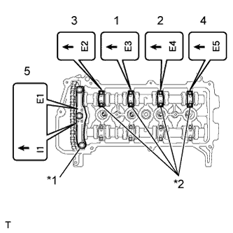 |
Examine the front marks and numbers on the No. 1 and No. 2 camshaft bearing caps and check that the order is as shown in the illustration. Then uniformly tighten the bolts, in several steps, in the sequence shown in the illustration.
| *1 | No. 1 Bearing Cap |
| *2 | No. 2 Bearing Cap |
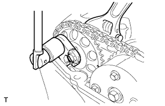 |
Using a union nut wrench 14 mm, hold the hexagonal lobe of the No. 2 camshaft and install the flange bolt.
Remove the bar from the timing chain tensioner.
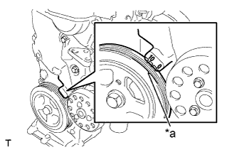 |
Turn the crankshaft damper and align the timing notch with the timing mark "0" of the oil pump.
| *a | Timing Notch |
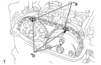 |
Check that all the pairs of timing marks are aligned.
| *a | Paint Mark |
| *b | Timing Mark |
Apply adhesive to 2 or 3 threads of the screw plug end.
Using an 8 mm (0.31 in.) hexagon wrench, install the screw plug.
| 4. INSTALL ENGINE MOUNTING INSULATOR SUB-ASSEMBLY RH |
Install the engine mounting insulator sub-assembly RH with the 4 bolts and 2 nuts.
| 5. INSTALL CYLINDER HEAD COVER SUB-ASSEMBLY |
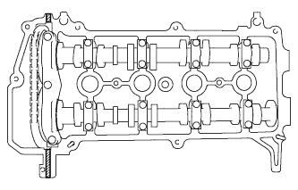 |
 | Seal Packing |
Apply seal packing to the cylinder head as shown in the illustration.
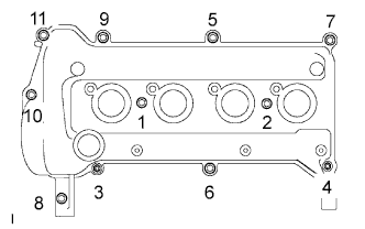 |
Install the cylinder head cover sub-assembly with the 9 bolts, 2 nuts and 2 seal washers.
Tighten the 9 bolts and 2 nuts in the sequence shown in the illustration.
Install the wire harness bracket with the bolt.
Connect the connector and 4 wire harness clamps and connect the engine wire harness.
Connect the 4 fuel injector connectors.
| 6. INSTALL NO. 1 IGNITION COIL |
Install the 4 No. 1 ignition coils with the 4 bolts.
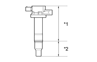 |
| *1 | Body |
| *2 | Cap |
Connect the 4 No. 1 ignition coil connectors.
| 7. CONNECT FUEL VAPOR FEED HOSE ASSEMBLY |
Connect fuel vapor feed hose assembly.
| 8. CONNECT VENTILATION HOSE |
Connect the ventilation hose.
| 9. INSPECT FOR OIL LEAK |
| 10. INSTALL ENGINE UNDER COVER RH |
| 11. INSTALL NO. 2 CYLINDER HEAD COVER |
Install the No. 2 cylinder head cover with the 4 nuts.