 |
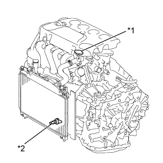
Loosen the radiator drain cock plug.
| *1 | Water Filler Cap Sub-assembly |
| *2 | Radiator Drain Cock Plug |
OIL PUMP (for Sedan) > REMOVAL |
| 1. DISCONNECT CABLE FROM NEGATIVE BATTERY TERMINAL |
| 2. REMOVE FRONT WHEEL RH |
| 3. REMOVE ENGINE UNDER COVER LH |
Remove the 3 bolts, the 4 screws and the engine under cover LH from the vehicle.
| 4. REMOVE ENGINE UNDER COVER RH |
Remove the 2 bolts, the 2 screws and the engine under cover RH from the vehicle.
| 5. DRAIN ENGINE OIL |
Remove the oil filler cap sub-assembly.
Remove the oil pan drain plug and the gasket from the No. 2 oil pan sub-assembly, and drain the engine oil into a container.
Clean and install the oil pan drain plug with a new gasket to the No. 2 oil pan sub-assembly.
| 6. DRAIN COOLANT |
|
Loosen the radiator drain cock plug.
| *1 | Water Filler Cap Sub-assembly |
| *2 | Radiator Drain Cock Plug |
Remove the water filler cap sub-assembly, then drain coolant.
| 7. REMOVE NO. 2 CYLINDER HEAD COVER |
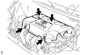 |
Remove the 4 nuts and cylinder head cover No. 2.
| 8. REMOVE FAN AND GENERATOR V BELT |
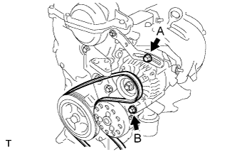 |
Loosen bolts A and B.
Release the fan and generator V belt tension and remove the fan and generator V belt.
| 9. REMOVE GENERATOR ASSEMBLY |
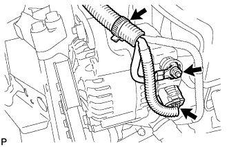 |
Remove the terminal cap.
Separate the connector and the harness clamp.
Remove the nut and remove terminal B.
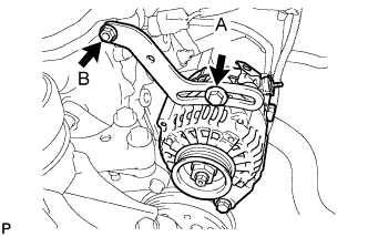 |
Remove fan belt adjusting slider fixing bolts A and B and remove the fan belt adjusting slider.
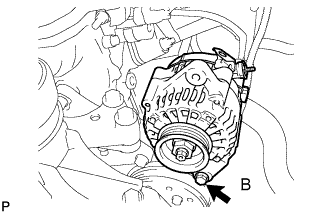 |
Remove fixing bolt B and remove the generator.
| 10. REMOVE NO. 1 IGNITION COIL |
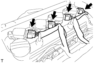 |
Disconnect the 4 ignition coil connectors.
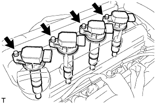 |
Remove the 4 bolts and 4 ignition coils.
| 11. DISCONNECT VENTILATION HOSE |
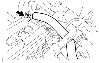 |
Disconnect the ventilation hose.
| 12. DISCONNECT FUEL VAPOR FEED HOSE ASSEMBLY |
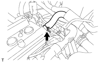 |
Disconnect fuel vapor feed hose assembly.
| 13. REMOVE CYLINDER HEAD COVER SUB-ASSEMBLY |
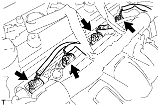 |
Disconnect the fuel injector connectors.
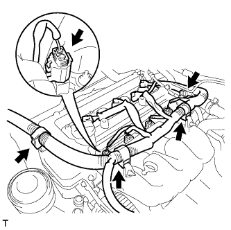 |
Disconnect the connector and 3 wire harness clamps shown in the illustration and disconnect the engine wire harness.
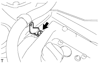 |
Remove the bolt and remove the wire harness bracket.
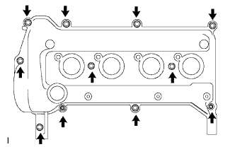 |
Remove the 9 bolts, 2 nuts and 2 seal washers and then remove the cylinder head cover sub-assembly.
Remove the gasket from the cylinder head cover sub-assembly.
| 14. REMOVE ENGINE MOUNTING INSULATOR SUB-ASSEMBLY RH |
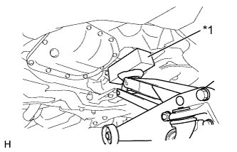 |
Place a wooden block on a jack underneath the oil pan sub-assembly.
| *1 | Wooden Block |
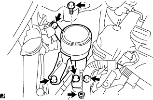 |
Remove the 5 bolts, the nut and the engine mounting insulator sub-assembly RH from the transverse engine engine mounting bracket and the vehicle.
| 15. REMOVE CRANKSHAFT DAMPER SUB-ASSEMBLY |
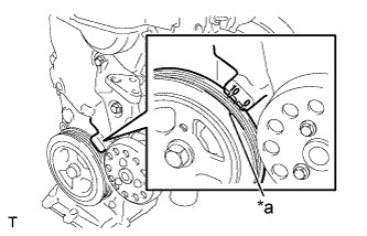 |
Set the No. 1 cylinder to TDC/compression.
Turn the crankshaft damper sub-assembly, and align its timing notch with timing mark "0" of the oil pump assembly.
| *a | Timing Mark |
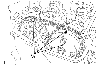 |
Check that the timing marks on the camshaft timing sprocket and the camshaft timing gear assembly are all facing upward as shown in the illustration.
| *a | Timing Mark |
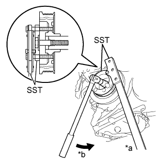 |
Using SST, loosen the bolt while holding the crankshaft damper sub-assembly.
| *a | Hold |
| *b | Turn |
Remove the SST and the bolt.
Remove the crankshaft damper sub-assembly from the crankshaft.
| 16. REMOVE CRANKSHAFT POSITION SENSOR |
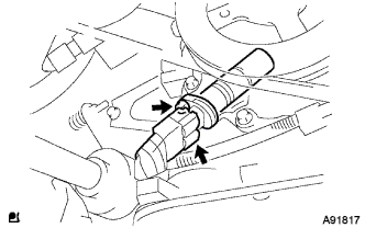 |
Disconnect the crankshaft position sensor connector.
Remove the bolt and remove the crankshaft position sensor.
| 17. REMOVE CAMSHAFT TIMING OIL CONTROL VALVE ASSEMBLY |
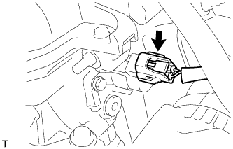 |
Disconnect the camshaft timing oil control valve assembly connector.
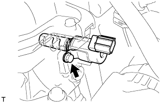 |
Remove the bolt and nut and remove the camshaft timing oil control valve assembly.
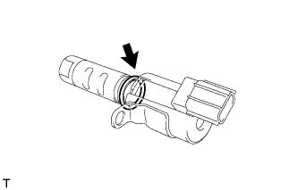 |
Remove the O-ring from the camshaft timing oil control valve assembly.
| 18. REMOVE WATER PUMP PULLEY |
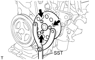 |
Using SST, hold the water pump pulley.
Remove the 3 bolts and remove the water pump pulley.
| 19. REMOVE ENGINE WATER PUMP ASSEMBLY |
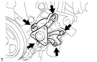 |
Remove the 3 bolts and 2 nuts and remove the engine water pump assembly and gasket.
| 20. REMOVE TRANSVERSE ENGINE ENGINE MOUNTING BRACKET |
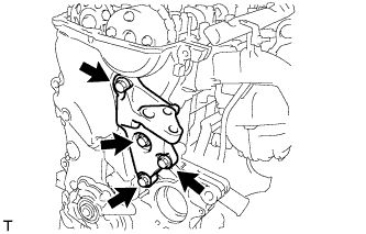 |
Remove the 4 bolts and the transverse engine engine mounting bracket from the oil pump assembly.
| 21. REMOVE OIL PUMP ASSEMBLY |
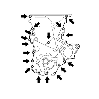 |
Remove the 16 bolts and the nut from the oil pump assembly.
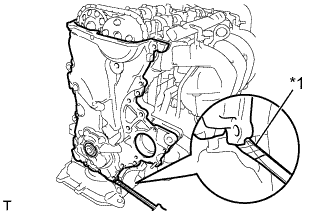 |
Using a screwdriver with its tip wrapped in protective tape, remove the oil pump assembly by prying between the cylinder head sub-assembly and cylinder block sub-assembly.
| *1 | Protective Tape |
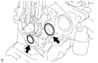 |
Remove the 2 O-rings from the cylinder block sub-assembly and the oil pan sub-assembly.