 |
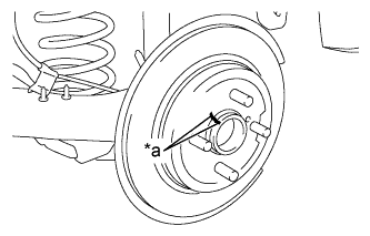
Align the matchmarks of the rear disc and axle hub and install the rear disc.
| *a | Matchmark |
- NOTICE:
- When replacing the disc with a new one, select the installation position where the rear disc has minimal runout.
REAR BRAKE (for Hatchback Disc Type) > INSTALLATION |
| 1. INSTALL REAR DISC |
|
Align the matchmarks of the rear disc and axle hub and install the rear disc.
| *a | Matchmark |
| 2. INSTALL REAR DISC BRAKE CYLINDER MOUNTING |
Install the rear disc brake cylinder mounting to the axle beam with the 2 bolts.
| 3. INSTALL REAR DISC BRAKE BUSHING DUST BOOT |
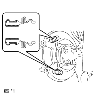 |
Apply a light layer of lithium soap base glycol grease to the entire circumference of 2 new rear disc brake bushing dust boots as shown in the illustration.
| *1 | Lithium Soap Base Glycol Grease |
Install the 2 rear disc brake bushing dust boots to the rear disc brake cylinder mounting.
| 4. INSTALL REAR DISC BRAKE CYLINDER SLIDE BUSH |
Install the 2 new slide bushes onto the 2 rear disc brake pad guide pins.
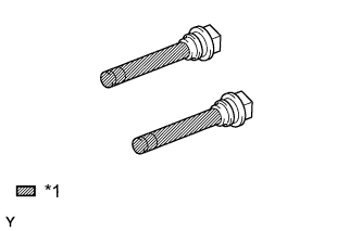 |
Apply a light layer of lithium soap base glycol grease to the entire circumference of the 2 rear disc brake pad guide pins as shown in the illustration.
| *1 | Lithium Soap Base Glycol Grease |
| 5. INSTALL REAR DISC BRAKE PAD GUIDE PIN |
Install the 2 rear disc brake pad guide pins to the rear disc brake cylinder mounting.
| 6. INSTALL REAR DISC BRAKE PAD SUPPORT PLATE |
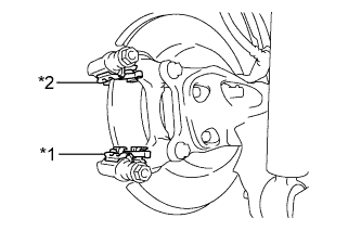 |
Install the No. 1 rear disc brake pad support plate and the No. 2 rear disc brake pad support plate to the rear disc brake cylinder mounting.
| *1 | No. 1 Rear Disc Brake Pad Support Plate |
| *2 | No. 2 Rear Disc Brake Pad Support Plate |
| 7. INSTALL REAR DISC BRAKE ANTI SQUEAL SHIM KIT |
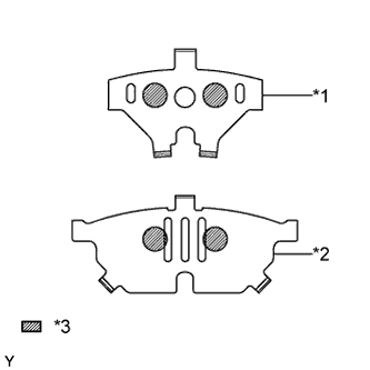 |
Apply disc brake grease to the inside of the 2 No. 1 rear disc brake anti squeal shims as shown in the illustration.
| *1 | No. 1 Rear Disc Brake Anti Squeal Shim (Inner) |
| *2 | No. 1 Rear Disc Brake Anti Squeal Shim (Outer) |
| *3 | Disc Brake Grease |
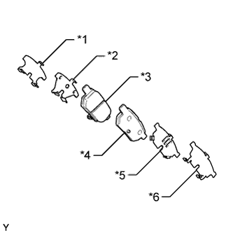 |
Install the 2 No. 1 rear disc brake anti squeal shims and the 2 No. 2 rear disc brake anti squeal shims to each brake pad.
| *1 | No. 2 Rear Disc Brake Anti Squeal Shim (Inner) |
| *2 | No. 1 Rear Disc Brake Anti Squeal Shim (Inner) |
| *3 | Rear Disc Brake Pad (w/ Indicator) |
| *4 | Rear Disc Brake Pad |
| *5 | No. 1 Rear Disc Brake Anti Squeal Shim (Outer) |
| *6 | No. 2 Rear Disc Brake Anti Squeal Shim (Outer) |
| 8. INSTALL REAR DISC BRAKE PAD KIT (PAD ONLY) |
Install the 2 rear disc brake pads to the rear disc brake cylinder mounting.
| 9. INSTALL REAR DISC BRAKE CYLINDER ASSEMBLY |
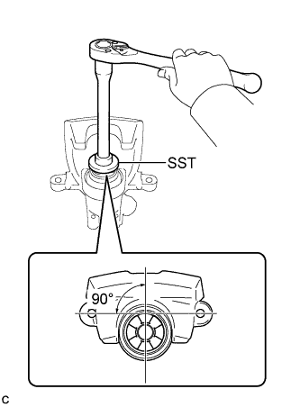 |
To compensate for pad wear when reusing the pad, use SST to push and turn the piston (LH side: counterclockwise, RH side: clockwise) to the position where the protrusion on the pad lines up properly with the piston groove.
Hold the rear disc brake pad guide pin, and install the rear disc brake cylinder assembly to the rear disc brake cylinder mounting with the 2 bolts.
| 10. CONNECT REAR BRAKE FLEXIBLE HOSE |
Connect the rear brake flexible hose to the rear disc brake cylinder assembly with a new union bolt and a new gasket.
| 11. CONNECT NO. 3 PARKING BRAKE CABLE ASSEMBLY |
Insert the parking brake cable into the disc brake cylinder and engage the clip claws of the parking brake cable to the rear disc brake cylinder guide.
Connect the cable end to the rear disc brake cylinder operation lever.
| 12. BLEED BRAKE LINE |
| 13. ADJUST PARKING BRAKE LEVER TRAVEL |
Remove the rear console box (Click here).
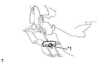 |
Turn the lock nut until the parking brake lever travel is corrected to within the specified range.
| *1 | Lock nut |
Operate the parking brake lever 3 to 4 times, and check the parking brake lever travel.
Check whether the parking brake drags or not.
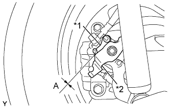 |
Release the parking brake lever and check that the clearance measurement between the rear disc brake cylinder operation lever and the stopper is within the specified range.
| *1 | Stopper |
| *2 | Operation Lever |
Install the rear console box (Click here).
| 14. INSTALL REAR CONSOLE BOX ASSEMBLY |
| 15. INSTALL REAR WHEEL |