EXHAUST MANIFOLD (for Sedan) > INSTALLATION |
| 1. INSTALL EXHAUST MANIFOLD |
|
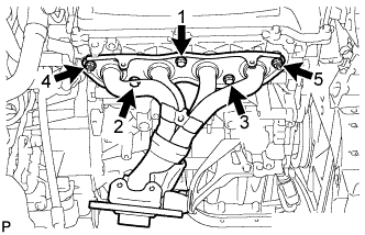
Tighten the nuts and bolts on the exhaust manifold, in the order shown in the illustration, through a new gasket.
| 2. INSTALL MANIFOLD SUPPORT BRACKET |
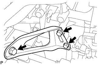 |
Install the manifold support bracket with the 3 bolts.
| 3. INSTALL NO. 1 EXHAUST MANIFOLD HEAT INSULATOR |
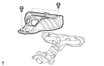 |
Install the No. 1 exhaust manifold heat insulator with the 4 bolts.
| 4. INSTALL FRONT EXHAUST PIPE ASSEMBLY |
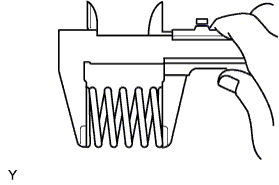 |
Using vernier calipers, measure the free length of the compression spring.
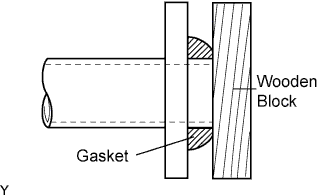 |
Using a plastic hammer and a wooden block, tap in a new exhaust pipe gasket until its surface is flush with the front exhaust pipe assembly.
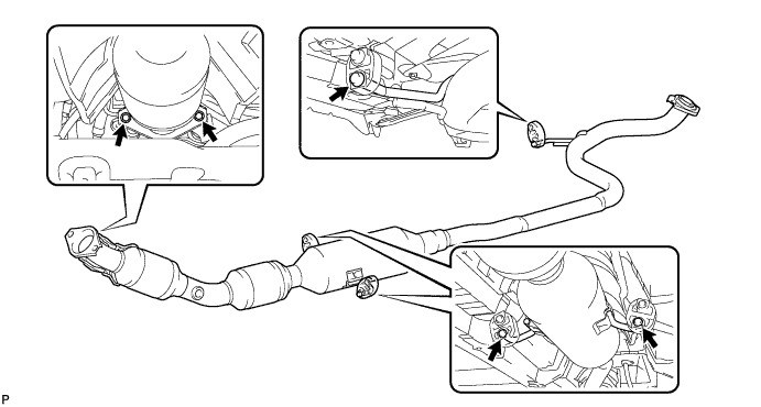
Install the 3 No. 4 exhaust pipe supports and front exhaust pipe assembly.
Install the exhaust front pipe assembly and a new exhaust pipe gasket with the 4 compression springs and 4 bolts.
| 5. INSTALL EXHAUST TAIL PIPE ASSEMBLY |
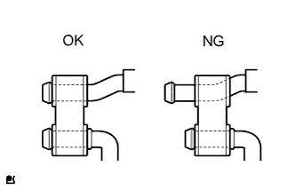 |
Check the No. 4 exhaust pipe supports.
Install the 3 No. 4 exhaust pipe supports and the exhaust tail pipe assembly.
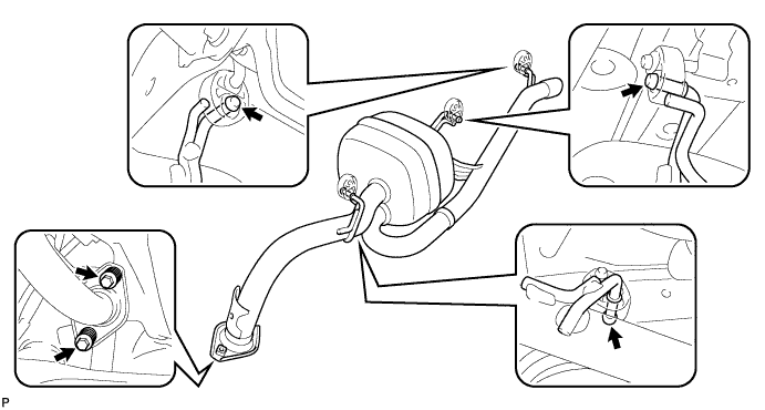
Install the 2 compression springs and 2 bolts.
| 6. INSTALL HEATED OXYGEN SENSOR |
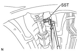 |
Using SST, install the heated oxygen sensor onto the front exhaust pipe.
Pass the sensor connector through the floor panel and install the grommet.
Connect the sensor connector.
| 7. INSTALL OUTER COWL TOP PANEL |
Install the cowl top panel outer with the 8 bolts.
Install the cowl top to cowl inner brace with the 2 bolts.
Connect the wire harness clamp.
| 8. INSTALL FRONT AIR SHUTTER SEAL |
Engage the 3 claws to install the front air shutter seal RH.
| 9. INSTALL FRONT WIPER MOTOR AND LINK |
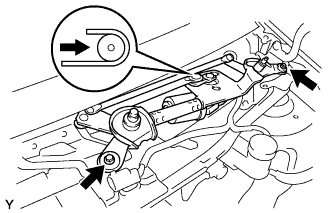 |
Connect the connector.
Slide the wiper link as shown in the illustration and engage the rubber pin with the body.
Install the front wiper motor and link with the 2 bolts.
| 10. INSTALL COWL TOP VENTILATOR LOUVER SUB-ASSEMBLY |
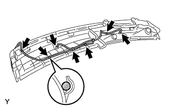 |
Connect the washer hoses.
Engage the 5 hooks.
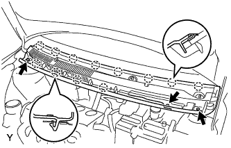 |
Engage the 8 hooks and the 4 claws.
Install the cowl top ventilator louver sub-assembly with the 3 clips.
| 11. INSTALL COWL SIDE VENTILATOR SUB-ASSEMBLY LH |
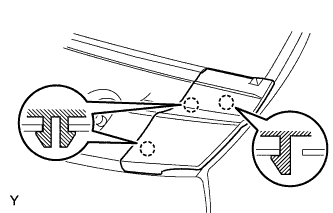 |
Engage the 3 claws and install the cowl side ventilator sub-assembly LH.
| 12. INSTALL COWL SIDE VENTILATOR SUB-ASSEMBLY RH |
| 13. INSTALL FRONT WIPER ARM AND BLADE ASSEMBLY LH |
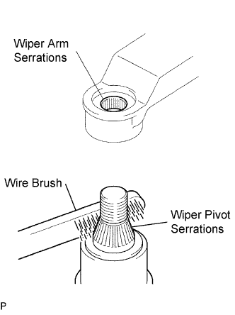 |
Scrape any metal powder off the serrated part of the wiper arm with a round file or the equivalent (when reinstalling).
Clean the wiper pivot serrations with a wire brush.
Operate the wiper, then stop the windshield wiper motor in the automatic stop position.
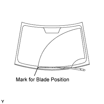 |
Align the blade tip with the mark on the windshield glass, as shown in the illustration.
Tighten the nut of the front wiper arm.
| 14. INSTALL FRONT WIPER ARM AND BLADE ASSEMBLY RH |
|
Scrape any metal powder off the serrated part of the wiper arm with a round file or the equivalent (when reinstalling).
Clean the wiper pivot serrations with a wire brush.
Operate the wiper, then stop the windshield wiper motor in the automatic stop position.
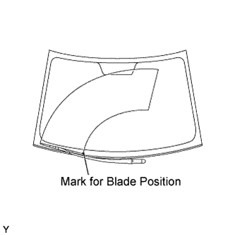 |
Align the blade tip with the mark on the windshield glass, as shown in the illustration.
Tighten the nut of the front wiper arm.
| 15. REMOVE FRONT WIPER ARM HEAD CAP |
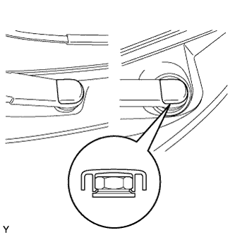 |
Engage the claw and install the 2 front wiper arm head caps.
| 16. INSTALL LOWER INSTRUMENT PAD LH |
Engage the claw and 3 clips and install the instrument pad lower.
Install the <H> screw.
| 17. INSTALL CONSOLE BOX ASSEMBLY |
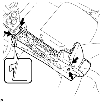 |
Engage the 4 claws and install the rear console box.
Install the 2 bolts and 2 screws.
Connect the clamp.
| 18. INSTALL CONSOLE BOX CARPET |
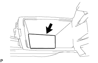 |
Install the console box carpet.
| 19. INSTALL CONSOLE BOX UPPER REAR PANEL SUB-ASSEMBLY |
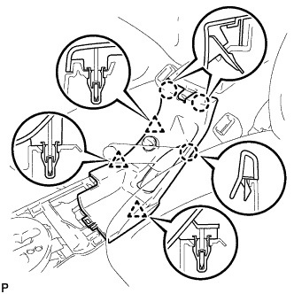 |
Connect the connector.
Engage the 3 clips and 3 claws and install the console upper rear panel.
| 20. INSTALL CONSOLE BOX UPPER PANEL SUB-ASSEMBLY |
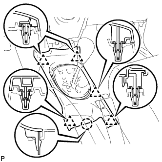 |
Engage the 5 clips and the claw and install the upper console panel.
| 21. INSTALL SHIFT LEVER KNOB SUB-ASSEMBLY (for Manual Transaxle) |
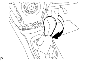 |
Install the shift lever knob.
| 22. INSTALL INSTRUMENT PANEL FINISH PANEL END LH |
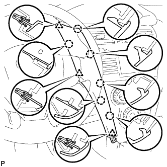 |
Engage the 6 claws and 3 clips and install the instrument panel finish panel end LH.
| 23. INSTALL INSTRUMENT PANEL LOWER CENTER FINISH PANEL |
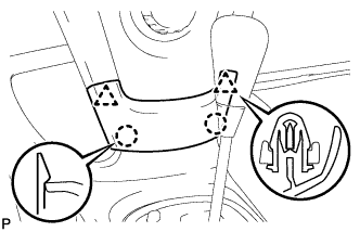 |
Engage the 2 claws and 2 clips and install the instrument panel finish panel lower center.
| 24. INSPECT FOR EXHAUST GAS LEAK |