 |
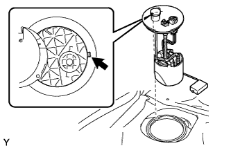
Align the tab of the fuel suction tube with pump and gauge assembly with the groove of the fuel tank assembly.
FUEL PUMP (for Sedan) > INSTALLATION |
| 1. INSTALL FUEL SUCTION TUBE SET GASKET |
Coat a new fuel suction tube gasket with gasoline and install it to the fuel tank assembly.
| 2. INSTALL FUEL SUCTION TUBE WITH PUMP AND GAUGE ASSEMBLY |
Pass the float of the fuel sender gauge assembly to the fuel tank assembly.
Bend up the tip of the fuel pump filter and set the fuel suction tube with pump and gauge assembly to the fuel tank assembly.
|
Align the tab of the fuel suction tube with pump and gauge assembly with the groove of the fuel tank assembly.
| 3. INSTALL FUEL PUMP GAUGE RETAINER |
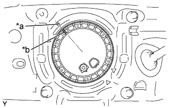 |
Align the retainer mark (start of threads) with the start of the threads on the fuel tank assembly, and while pressing down on the fuel suction tube with pump and gauge assembly, install a new fuel pump gauge retainer and tighten it by hand as much as possible.
| *a | Start of Threads (Fuel Tank Assembly) |
| *b | Start of Threads Fuel Pump Gauge Retainer) |
Install SST to the fuel pump gauge retainer.
Temporarily install SST (plate) and SST (claw) to the fuel pump gauge retainer.
Press SST (claw) against the rib of the fuel pump gauge retainer, and tighten SST (bolt).
Install SST (handle).
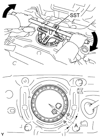 |
While making sure that SST does not rise up, slowly turn SST (handle) and tighten until the mark on the fuel pump gauge retainer is within range A as shown in the illustration.
| 4. CONNECT FUEL TANK VENT HOSE |
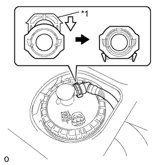 |
Connect the fuel tank vent hose to the fuel suction tube with pump and gauge assembly and lock it by pushing in the retainer.
| *1 | Retainer |
 | Push |
| 5. CONNECT FUEL TANK MAIN TUBE SUB-ASSEMBLY |
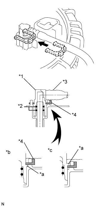 |
Insert the fuel tank main tube sub-assembly.
Install the tube joint clip to connect the fuel tank main tube sub-assembly.
| *1 | Fuel Tube Joint |
| *2 | O-ring |
| *3 | Fuel Tube |
| *4 | Tube Joint Clip |
| *a | Rib |
| *b | OK |
| *c | NG |
| 6. INSTALL REAR FLOOR SERVICE HOLE COVER |
Connect the fuel pump connector.
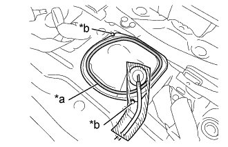 |
Apply butyl tape to the location shown in the illustration, align the 2 alignment marks, and install the rear floor service hole cover.
| *a | Butyl Tape |
| *b | Alignment Mark |
| 7. INSPECT FOR FUEL LEAK |
When using the Techstream.
Connect the Techstream to the DLC3.
Turn the ignition switch to ON and turn the tester ON.
Select the following menu items: Powertrain / Engine and ECT / Active Test / Control the Fuel Pump / Speed.
Check that there is no fuel leakage anywhere on the fuel system after doing maintenance.
| 8. INSTALL REAR SEAT CUSHION COVER PAD SUB-ASSEMBLY (for 60/40 Split Seat Type) |
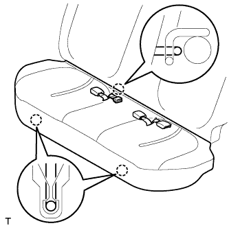 |
Pass the rear seat inner belt through the rear seat cushion cover pad slit.
Engage the 3 hooks and install the rear seat cushion cover pad.
| 9. CONNECT CABLE TO NEGATIVE BATTERY TERMINAL |