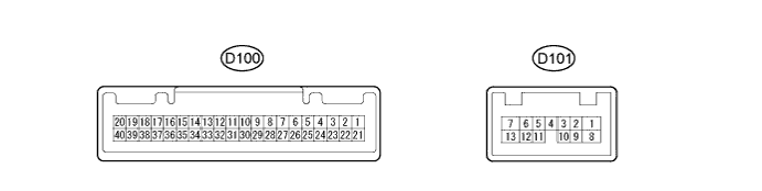
SEAT BELT WARNING SYSTEM (for Hatchback) > TERMINALS OF ECU |
| COMBINATION METER ASSEMBLY |
Disconnect the D100 combination meter assembly connector.
Measure the voltage and resistance according to the value(s) in the table below.
| Terminal No. (Symbol) | Wiring Color | Terminal Description | Switch Condition | Specified Condition |
| D100-39 (IG+) - Body ground | P - Body ground | Ignition switch signal | Ignition switch off → ON | Below 1 V → 11 to 14 V |
| D100-40 (B) - Body ground | L - Body ground | Battery | Always | 11 to 14 V |
| D100-21 (ET) - Body ground | W-B - Body ground | Ground | Always | Below 1 Ω |
Reconnect the combination meter assembly connector.
Measure the check for pulse according to the value(s) in the table below.
| Terminal No. (Symbol) | Wiring Color | Terminal Description | Switch Condition | Specified Condition |
| D100-31 (CANL) - Body ground | W - Body ground | CAN communication line | Ignition switch ON | Pulse generation |
| D100-32 (CANH) - Body ground | G - Body ground | CAN communication line | Ignition switch ON | Pulse generation |
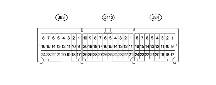
| AIRBAG SENSOR ASSEMBLY (for Hatchback with VSC) |
| Terminal No. | Terminal Symbol | Destination |
| D112-13 | CANH | Combination meter assembly (Meter ECU) |
| D112-22 | CANL | Combination meter assembly (Meter ECU) |
| J83-10 | LBE+ | Front seat inner belt LH (Seat belt buckle switch LH) |
| J83-18 | LBE- | Front seat inner belt LH (Seat belt buckle switch LH) |
| J84-16 | FSR+ | Occupant classification ECU |
| J84-24 | FSR- | Occupant classification ECU |
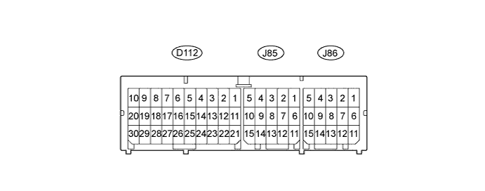
| AIRBAG SENSOR ASSEMBLY (for Hatchback without VSC) |
| Terminal No. | Terminal Symbol | Destination |
| D112-13 | CANH | Combination meter assembly (Meter ECU) |
| D112-22 | CANL | Combination meter assembly (Meter ECU) |
| J85-11 | LBE+ | Front seat inner belt LH (Seat belt buckle switch LH) |
| J85-12 | LBE- | Front seat inner belt LH (Seat belt buckle switch LH) |
| J86-12 | FSR+ | Occupant classification ECU |
| J86-13 | FSR- | Occupant classification ECU |
| OCCUPANT CLASSIFICATION ECU |

Measure the voltage and check for pulse according to the value(s) in the table below.
| Terminal No. | Wiring Color | Terminal Description | Switch Condition | Specified Condition |
| X3-1 - X3-5 | GR - W | Rear occupant classification sensor LH power supply line | Ignition switch ON | 4.9 to 5.1 V |
| X3-2 - X3-6 | V - BR | Rear occupant classification sensor RH power supply line | Ignition switch ON | 4.9 to 5.1 V |
| X3-3 - X3-5 | SB - W | Rear occupant classification sensor LH signal line | Ignition switch ON | Pulse generation |
| X3-4 - X3-6 | B - BR | Rear occupant classification sensor RH signal line | Ignition switch ON | Pulse generation |
| X3-5 - X4-3 | W - W-B | Rear occupant classification sensor LH ground line | Always | Below 1 V |
| X3-6 - X4-3 | BR - W-B | Rear occupant classification sensor RH ground line | Always | Below 1 V |
| X4-1 - X4-3 | W - W-B | Battery power supply | Always | 11 to 14 V |
| X4-2 - X4-3 | GR - W-B | Diagnosis (DLC3) | Ignition switch ON | Below 1 V |
| X4-3 - Body ground | W-B - Body ground | Ground | Always | Below 1 V |
| X4-6 - X4-3 | B - W-B | Ignition switch power supply | Ignition switch ON | 11 to 14 V |
| X4-7 - X4-4 | L - LG | Airbag sensor assembly communication line | Ignition switch ON | Pulse generation |
| X4-8 - X4-5 | G - P | Front passenger side buckle switch line | Ignition switch ON | Pulse generation |