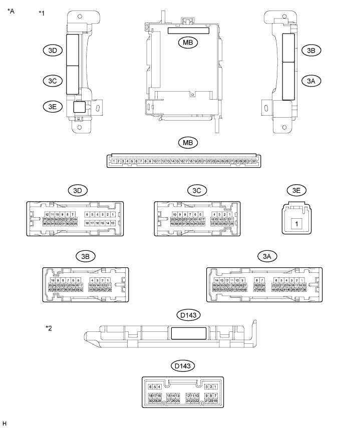
LIGHTING SYSTEM (for Hatchback) > TERMINALS OF ECU |
| CHECK INSTRUMENT PANEL JUNCTION BLOCK ASSEMBLY AND MAIN BODY ECU |
| *A | Main Body ECU 1 Connector Type | - | - |
| *1 | Instrument Panel Junction Block Assembly | *2 | Main Body ECU |
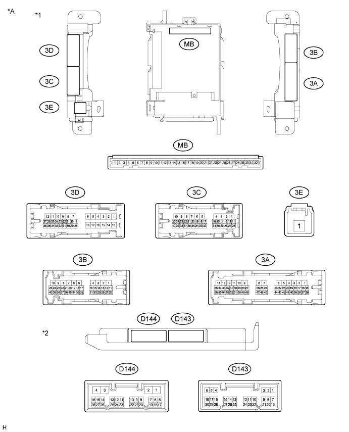
| *A | Main Body ECU 2 Connector Type | - | - |
| *1 | Instrument Panel Junction Block Assembly | *2 | Main Body ECU |
Remove the main body ECU.
Measure the voltage and resistance according to the value(s) in the table below.
| Terminal No. (Symbol) | Wiring Color | Terminal Description | Condition | Specified Condition |
| MB-11 (GND1) - Body ground | - | Ground | Always | Below 1 Ω |
| MB-29 (ACC) - Body ground | - | Ignition power supply (ACC signal) | Ignition switch ACC | 11 to 14 V |
| MB-30 (BECU) - Body ground | - | Battery power supply | Always | 11 to 14 V |
| MB-32 (IG) - Body ground | - | Ignition power supply (IG signal) | Ignition switch ON | 11 to 14 V |
Reinstall the main body ECU.
Measure the voltage and resistance according to the value(s) in the table below.
| Terminal No. (Symbol) | Wiring Color | Terminal Description | Condition | Specified Condition |
| D143-5 (HU) - Body ground*1 | P - Body ground | Dimmer switch high signal | Dimmer switch in high position | Below 1 V |
| Dimmer switch in low position | Pulse generation | |||
| D143-8 (HF) - Body ground*1 | P - Body ground | Dimmer switch high flash signal | Dimmer switch in high flash position | Below 1 V |
| Dimmer switch not in high flash position | Pulse generation | |||
| D143-13 (CANL) - Body ground | W - Body ground | CAN communication | Ignition switch ON | Pulse generation |
| D143-14 (CANH) - Body ground | R - Body ground | CAN communication | Ignition switch ON | Pulse generation |
| D143-27 (FFOG) - Body ground*1, *2 | G - Body ground | Fog light switch signal | Fog light switch on | Below 1 V |
| Fog light switch off | Pulse generation | |||
| D143-28 (A) - Body ground*4 | V - Body ground | Light control switch daytime running light off signal | Light control switch in DRL position | Below 1 V |
| Light control switch not in DRL position | Pulse generation | |||
| D143-29 (HEAD) - Body ground*1 | L - Body ground | Light control switch head signal | Light control switch in head position | Below 1 V |
| Light control switch not in head position | Pulse generation | |||
| D143-30 (TAIL) - Body ground)*1 | SB - Body ground | Light control switch tail signal | Light control switch in tail or head position | Below 1 V |
| Light control switch in neither tail nor head position | Pulse generation | |||
| 3A-28 (PKB) - Body ground | R - Body ground | Parking brake switch input | Parking brake switch ON and ignition switch ON | Below 1 V |
| Parking brake switch off and ignition switch ON | 11 to 14 V | |||
| 3C-18 (HRLY) - Body ground*1 | V - Body ground | Headlight relay drive output | Light control switch in head position | Below 1 V |
| Light control switch not in head position | 11 to 14 V | |||
| 3C-22 (DRL) - Body ground*3 | G - Body ground | Daytime running light system drive output | Daytime running light system operates | Below 1 V |
| Daytime running light system does not operate | 11 to 14 V | |||
| 3C-35 (DIM) - Body ground*1 | P - Body ground | Dimmer relay drive output | Dimmer switch in high or high flash position | Below 1 V |
| Dimmer switch in low position | 11 to 14 V |
| CHECK COMBINATION METER ASSEMBLY |

Disconnect the D101 combination meter assembly connector.
Measure the voltage according to the value(s) in the table below.
| Terminal No. (Symbol) | Wiring Color | Terminal Description | Condition | Specified Condition |
| D101-1 (B) - Body ground | R - Body ground | Battery power supply | Always | 11 to 14 V |
Reconnect the combination meter assembly connector.
Measure the voltage according to the value(s) in the table below.
| Terminal No. (Symbol) | Wiring Color | Terminal Description | Condition | Specified Condition |
| D101-3 (HAZ) - Body ground | L - Body ground | Hazard warning signal switch signal | Hazard warning signal switch off | 11 to 14 V |
| Hazard warning signal switch on | Below 1 V | |||
| D101-7 (LR) - Body ground | V - Body ground | Turn signal light RH drive output | Turn signal light RH turned on | 11 to 14 V |
| Turn signal light RH turned off | Below 1 V | |||
| D101-9 (ER) - Body ground | B - Body ground | Turn signal switch RH signal | Turn signal switch RH on | Below 1 V |
| Turn signal switch RH off | 11 to 14 V | |||
| D101-10 (EL) - Body ground | Y - Body ground | Turn signal switch LH signal | Turn signal switch LH on | Below 1 V |
| Turn signal switch LH off | 11 to 14 V | |||
| D101-13 (LL) - Body ground | LG - Body ground | Turn signal light LH drive output | Turn signal light LH turned on | 11 to 14 V |
| Turn signal light LH turned off | Below 1 V |