Home › Engine / Hybrid System › 1NZ-FE STARTING › STARTER (for Hatchback for Cold Area Specification Vehicles)

STARTER (for Hatchback for Cold Area Specification Vehicles) > REASSEMBLY


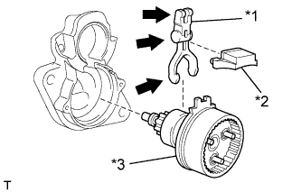
1. INSTALL STARTER CENTER BEARING CLUTCH SUB-ASSEMBLY


    A257712E02
  1. Apply high-temperature grease to the parts of the starter pinion drive lever that contact the starter pivot part of the starter pinion drive lever.
    Text in Illustration 
    *1
    Starter Pinion Drive Lever
    *2
    Rubber Seal
    *3
    Starter Center Bearing Clutch Sub-Assembly
    V100135
    High-temperature grease

  1. Install the starter pinion drive lever and rubber seal into the starter center bearing clutch sub-assembly.

  1. Install the starter center bearing clutch together with the starter pinion drive lever into the starter drive housing assembly.


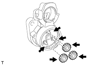
2. INSTALL PLANETARY GEAR


    A257717E01
  1. Apply high-temperature grease to the planetary gears and pin parts of the planetary shaft.
    Text in Illustration 
    V100135
    High-temperature grease

  1. Install the 3 planetary gears.


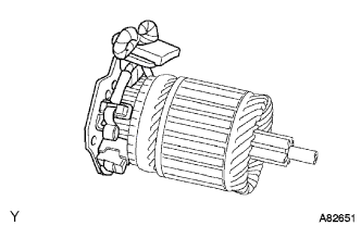
3. INSTALL STARTER BRUSH HOLDER ASSEMBLY


    A082651
  1. Install the brush holder.

    1. Using a screwdriver, hold the brush springs back, and install the 4 brushes into the brush holder.

    2. Install the brush holder to the starter armature.


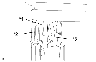
    3. A187223E08
    4. Insert the grommet between the positive (+) pole and negative (-) pole.
      Text in Illustration 
      *1
      Grommet
      *2
      - Pole
      *3
      + Pole


4. INSTALL STARTER COMMUTATOR END FRAME ASSEMBLY


    A169158
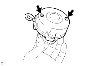
  1. Fit the clamp of the brush holder into the starter commutator end frame assembly.


    A169159
  1. Install the commutator end frame with the 2 screws.

    Torque:
    1.5 N*m{ 15 kgf*cm , 13 in.*lbf }


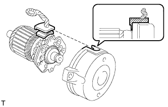
5. INSTALL STARTER ARMATURE ASSEMBLY
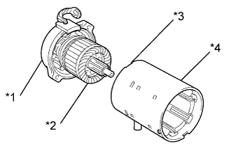
  1. Align the rubber with the groove of the starter yoke assembly.


    A257718E01
  1. Install the starter armature with the brush holder onto the starter yoke assembly.

    NOTICE:
    The magnet of the starter yoke assembly may attract the starter armature assembly when the starter commutator end frame assembly is installed, causing the magnet to break.

    HINT:
    Support the starter armature so that it may not be pulled out from the starter brush holder by magnetic force of the starter yoke assembly.

    Text in Illustration 
    *1
    Starter Commutator End Frame Assembly
    *2
    Starter Armature Assembly
    *3
    Groove
    *4
    Starter Yoke Assembly


6. INSTALL STARTER ARMATURE PLATE
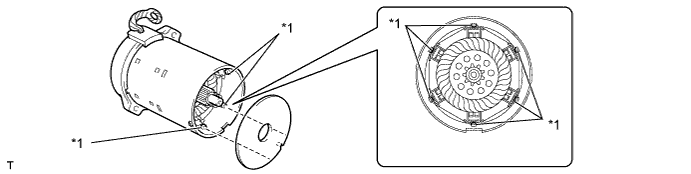
  1. Install the starter armature plate onto the starter yoke assembly.


  1. Install the starter plate so that the keyway is positioned between the keys.


    A257719E01


    Text in Illustration 
    *1
    Key
    -
    -


7. INSTALL STARTER COMMUTATOR END FRAME ASSEMBLY


    A257720E01
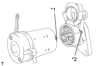
  1. Align the key of the starter yoke with the keyway located on the starter drive housing assembly.
    Text in Illustration 
    *1
    Key
    *2
    Keyway


    A257706
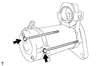
  1. Using a T25 "TORX" socket wrench, install the drive housing with the 2 bolts.

    Torque:
    6.0 N*m{ 61 kgf*cm , 53 in.*lbf }


8. INSTALL MAGNET STARTER SWITCH ASSEMBLY
  1. Apply high-temperature grease to the plunger hook.


    A257705
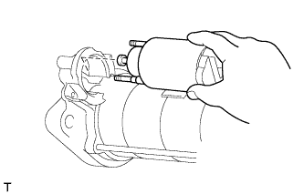
  1. Hang the plunger of the magnet starter switch assembly into the drive lever from the upper side.


    A257704
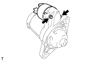
  1. Install the magnet starter switch assembly with the 2 nuts.

    Torque:
    7.5 N*m{ 77 kgf*cm , 66 in.*lbf }


    A188714
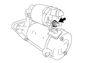
  1. Connect the lead wire to the magnet starter switch, then fasten it with the nut.

    Torque:
    10 N*m{ 102 kgf*cm , 7.4 ft.*lbf }