EXTERIOR PANELS / TRIM BODY STRUCTURE DETAILS SAFETY FEATURES
CONSTRUCTION
Impact Absorbing Structure for Front Collisions
A body structure ensures efficient impact energy absorption and dissipation by the frames from the front to under body to soften the impact to the passengers and minimizes cabin deformation by the rigid cabin frames, in the event of a frontal collision.
Impact energy during a frontal collision will first be dispersed into the left and right front side members by the front bumper reinforcement. Then it will be dispersed again into the rocker reinforcements and under frames via the front torque boxes.
Impact energy from the upper members will be dispersed into the front door beltline reinforcements and front pillar reinforcement sub-assembly via the Minimum Intrusion Cabin System (MICS) bulks and then distributed to the roof side rail sub-assembly.
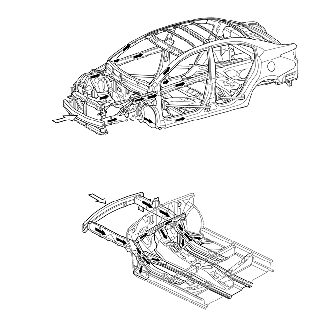
| *1 | Front Bumper Reinforcement Sub-assembly | *2 | Minimum Intrusion Cabin System (MICS) Bulks |
| *3 | Front Pillar Reinforcement Sub-assembly | *4 | Front Side Member Sub-assembly |
| *5 | Rocker Reinforce Sub-assembly | *6 | Front Door Beltline Reinforcement |
| *7 | Front floor kick Reinforcement | *8 | Front Panel Member Sub-assembly |

|
Path of Collision Energy | 
|
Frontal Collision |
Dash panel insulator pads are provided in the lower section of the dash panel to lessen the impact to the legs of the front passengers.
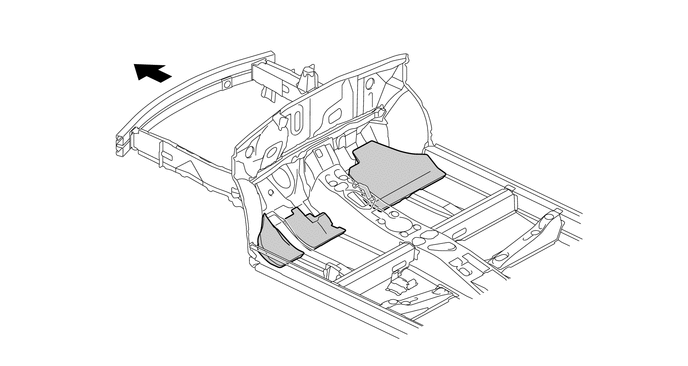
| *1 | Dash Panel Sub-assembly | *2 | Accelerator Pedal Area (No. 2 Dash Panel Insulator Pad) |
| *3 | Foot Rest Area (No. 3 Dash Panel Insulator Pad) | *4 | Passenger Seat (No. 4 Dash Panel Insulator Pad) |
|
|
Front | - | - |
Impact Absorbing Structure for Side Collision
A structure that ensures collision energy absorption efficiency, dissipates impact, and minimizes cabin deformation during a side collision has been achieved.
Bulkheads are placed inside the rocker reinforcements to efficiently transmit impact energy to the front floor cross members as well as preventing the rocker reinforcement deformation.
Optimal placement of the door side impact protection beams enables a construction that efficiently transmits load.
Energy absorbing pads are used inside the door trims to dampen the impact energy applied to the abdomen and pelvis of the occupant in a side collision. The impact load applied from the side of the front door side impact protection beam will be released to the opposite side of the body via the front seat rod.
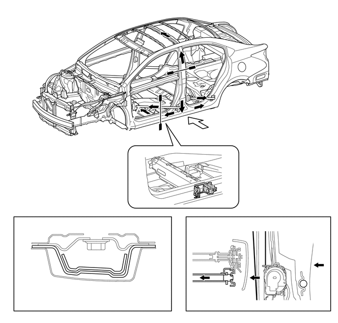
| *1 | Roof Side Rail Sub-assembly | *2 | Roof Panel Reinforcement |
| *3 | Center Body Pillar Outer Reinforcement | *4 | Front Door Side Impact Protection Beam |
| *5 | Rear Door Side Impact Protection Beam | *6 | Bulkhead |
| *7 | Center Body Pillar Upper Hinge Reinforcement | *8 | Center Body Pillar Outer Reinforcement |
| *9 | Front Seat Rod | *10 | Front Seat Outer Belt Assembly |
| *a | A-A Cross Section | *b | B-B Cross Section |
|
|
Path of Collision Energy |
|
Side Collision |
Lessening Pedestrian Injury
The hood panel, front fender, cowl top panel and front bumper are designed to absorb impact energy to dampen the impact applied to the head and legs of a pedestrian in case of a collision.
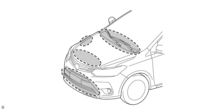
| *a | Cowl Top Panel Area | *b | Front Fender Area |
| *c | Hood Panel Area | *d | Front Bumper Area |
Ridges are provided in appropriate positions of the hood inner panel and hood reinforcement respectively, in order to lessen the impact energy to a pedestrian during a collision by allowing both structures to collapse and to absorb the impact energy.
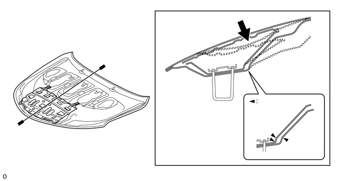
| *1 | Hood Reinforcement | *2 | Hood Panel |
| *3 | Hood Inner Panel | *4 | Hood Lock Striker |
| *a | A-A Cross Section | *b | Ridges |
|
|
Impact | - | - |
An impact absorbing bracket is used for the mounting portion of the front fender panel to absorb impact energy to the head of the pedestrian in a collision, thus dampening the impact to the head.
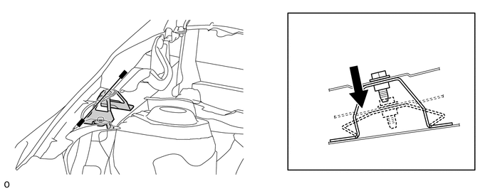
| *1 | Front Fender Panel (Front Fender Sub-assembly) | *2 | Impact Absorbing Bracket |
| *a | A-A Cross Section | - | - |
|
|
Impact | - | - |
An open section structure is used for the cowl, which efficiently absorbs the impact energy applied from the estimated direction of a collision with the head of a pedestrian, thus reducing the injury rate. In order to reduce the impact applied from above, the cowl employs a crushable structure with collapsible ridges that are considerably arranged.
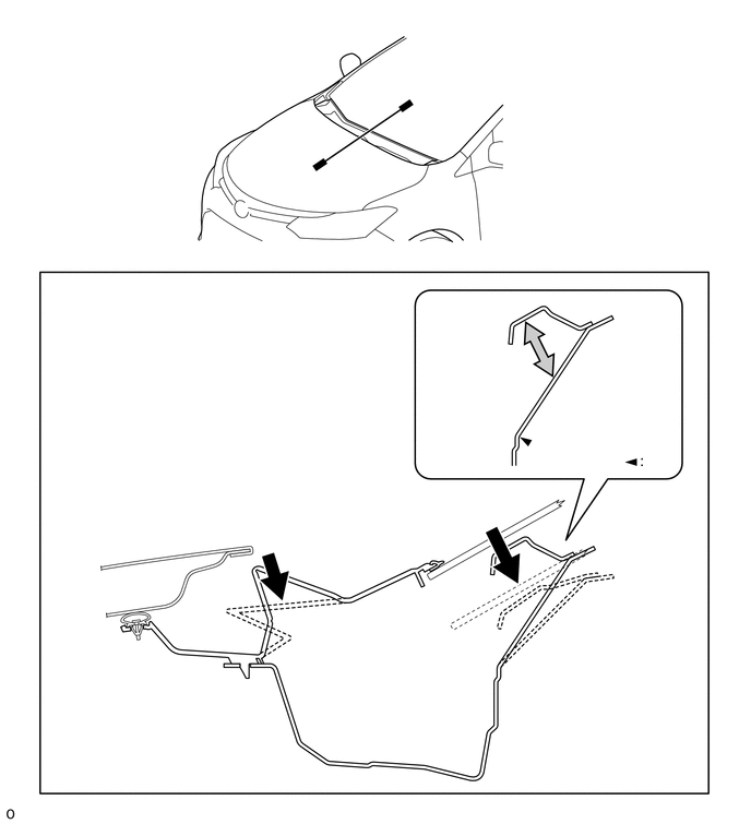
| *1 | Hood Panel | *2 | Cowl Top Ventilator Louver Sub-assembly |
| *3 | Cowl Top Panel Inner | - | - |
| *a | A-A Cross Section | *b | Open Section Structure |
| *c | Ridges | - | - |
|
|
Impact | - | - |