U441E AUTOMATIC TRANSMISSION / TRANSAXLE AUTOMATIC TRANSAXLE SYSTEM CONTROL AUTOMATIC TRANSAXLE CONTROL
FUNCTION OF MAIN COMPONENTS
The main components of the U441E automatic transaxle system are as follows:
| Component | Function |
|---|---|
| Forward Clutch (C1) | Connects the input shaft and front planetary sun gear. |
| Direct Clutch (C2) | Connect the input shaft and planetary carrier. |
| Reverse Clutch (C3) | Connect the input shaft and rear planetary sun gear. |
| OD and 2nd Brake (B1) | Locks the rear planetary sun gear. |
| 2nd Brake (B2) | Prevents the rear planetary sun gear from turning counterclockwise. |
| 1st and Reverse Brake (B3) | Locks the planetary carrier. |
| No. 1 1-way Clutch (F1) | Prevents the rear planetary sun gear from turning counterclockwise. |
| No. 2 1-way Clutch (F2) | Prevents the planetary carrier from turning counterclockwise. |
| Planetary Gears | Change the route through which driving force is transmitted, in accordance with the operation of both clutch and brake, in order to increase or reduce the input and output speed. |
| Shift Solenoid Valve S1 | ·
Switches the 2-3 shift valve. ·
Controls the C2 clutch. |
| Shift Solenoid Valve S2 | ·
Switches the 1-2 and 3-4 shift valves. ·
Controls the C1clutch and 2 brakes (B1 and B2). |
| Shift Solenoid Valve ST | ·
Switches the 3-4 shift timing valve. ·
Switches the No. 1 4-3 shift timing valve. |
| Shift Solenoid Valve SL | Controls the lock-up clutch. |
| Shift Solenoid Valve SLT | ·
Controls the line pressure. ·
Controls the secondary pressure. ·
Controls the accumulator backpressure. |
| ATF Temperature Sensor (Transmission Wire) | Detects the ATF temperature. |
| Speed Sensor NT (Transmission Revolution Sensor) | Detects the input speed of the transaxle. |
| Park/Neutral Position Switch Assembly | Detects the shift lever position. |
| Transmission Control Switch | Detects the shift lever in 3 position. |
| Shift Lock Control ECU Sub-assembly | Controls the shift lock system. |
| Stop Light Switch Assembly | Detects the brake pedal depressed. |
| Combination Meter Assembly | Detects the vehicle speed signal. |
| MIL | Illuminates or blinks to inform the driver when the ECM detects a malfunction. |
| Shift Position Indicator | Indicates the shift lever position. |
| ECM | ·
Controls each shift solenoid valve and engine output in response to a signal from each sensor and switch. ·
When the ECM detects a malfunction, it makes a diagnosis and memorizes the failed section. |
SYSTEM CONTROL
Automatic Transaxle Controls List
| Control | Outline |
|---|---|
| Clutch to Clutch Pressure Control | Calculates an environmentally favorable shift position based on the driving conditions of the vehicle, and gives shifting recommendation. |
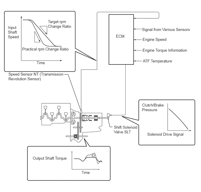
| Clutch Pressure Control | The shift solenoid valve SLT minutely controls the clutch pressure in accordance with the engine output and driving conditions. |
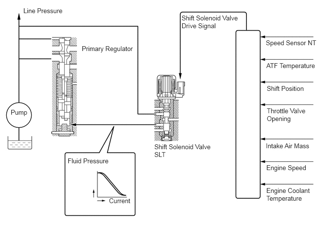
| Line Pressure Control | Actuates the shift solenoid valve SLT to control the line pressure in accordance with information from the ECM and the operating conditions of the transaxle. |
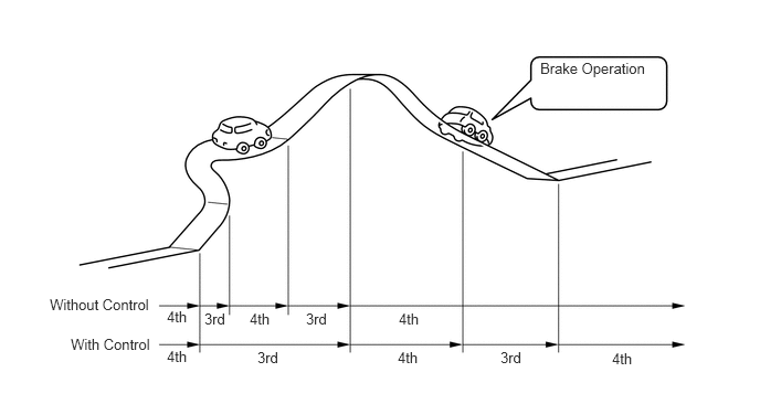
| Shift Control in Uphill/Downhill Traveling | Controls to restrict the 4th upshift or to provide appropriate engine braking by using the ECM to determine whether the vehicle is traveling on uphill or downhill. |
| Shift Timing Control | The ECM sends current to the shift solenoid valve S1 and/or S2 based on signals from each sensor and shifts the gear. |
| Lock-up Timing Control | The ECM sends current to the shift solenoid valve SL based on the signals from each sensor and engages or disengages the lock-up clutch. |
| Engine Torque Control | Temporarily retards the engine ignition timing to restrict the output torque, thus ensuring the shift feel during up or down shifting. |
| "N" to "D" Squat Control | When the shift lever is shifted from the "N" to "D" position, the gear is temporarily shifted to the 3rd and then to the 1st to reduce vehicle squat. |
| Shift Lock System | The shift lock mechanism prevents the shift lever from being moved to any position other than P, unless the ignition switch is ON, and the brake pedal is depressed. |
| Fail-safe | Even if a malfunction is detected in the sensors or solenoids, the ECM effects fail-safe control to prevent the vehicle's drivability from being affected significantly. |
| Diagnosis | When the ECM detects a malfunction, the ECM makes a diagnosis and memorizes the failed section. |
Clutch to Clutch Pressure Control
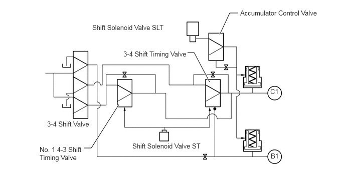
This control is used for shifting from 3rd to 4th gear, and from 4th to 3rd gear. It actuates shift solenoid valves ST and SLT in accordance with the signals from the ECM, and guides this output pressure directly to the No. 1 4-3 shift timing valve and the 3-4 shift timing valve in order to regulate the line pressure that acts on the B1 brake (OD and 2nd brake) and C1 clutch (forward clutch). As a result, smooth shift characteristics are delivered.
The B1 and C1 accumulators are made compact.
Clutch Pressure Control
The ECM monitors the signals from various types of sensor such as the speed sensor NT (transmission revolution sensor), allowing shift solenoid valve SLT to minutely control the clutch pressure in accordance with engine output and driving conditions. As a result, smooth shift characteristics have been realized.
Line Pressure Control
Through the use of the shift solenoid valve SLT, the line pressure is appropriately controlled in accordance with the engine torque information, as well as with the internal operating conditions of the torque converter assembly and the transaxle.
Accordingly, the line pressure can be controlled minutely in accordance with the engine output, traveling condition and the ATF temperature, thus realizing smooth shift characteristics and regulating the workload in the oil pump.
Shift Control in Uphill/Downhill Traveling
This control helps minimize the gear shifting when the driver operates the accelerator pedal while driving on a winding uphill or downhill road in order to ensure a smooth drive.
When the ECM detects uphill travel, it prohibits upshifting to 4th after downshifting to 3rd.
If a signal indicating that the driver has operated the brake pedal is input while the ECM detects downhill travel, it downshifts from 4th to 3rd.
The actual acceleration calculated from the speed sensor signal is compared with the reference acceleration (based on level road travel) stored in the ECM to determine uphill or downhill travel.

| *a | Smaller | - | - |

|
Reference Acceleration | 
|
Actual Acceleration |

| *a | Greater | - | - |
|
|
Reference Acceleration |
|
Actual Acceleration |
FAIL-SAFE
The fail-safe function minimizes the loss of operability when an abnormality occurs in a sensor or shift solenoid valve.
| Malfunction Part | Function |
|---|---|
| Vehicle Speed Signal | During a vehicle speed signal malfunction, the 4th upshift is prohibited. |
| Speed Sensor NT (Transmission Revolution Sensor) | During a speed sensor NT (transmission revolution sensor) signal malfunction, the 4th upshift is prohibited. |
| ATF Temperature Sensor (Transmission Wire) | During a ATF temperature sensor (transmission wire) malfunction, the 4th upshift is prohibited. |
| Shift Solenoid Valve SLT or ST | During a shift solenoid valve SLT or ST malfunction, the 4th upshift is prohibited. |
| E.F.I. Engine Coolant Temperature Sensor, Knock Control Sensor or Throttle Position Sensor | During an E.F.I. engine coolant temperature sensor, knock control sensor or throttle position sensor malfunction, the 4th upshift is prohibited. |
| Shift Solenoid Valve S1 or S2 | During a malfunction in the shift solenoid valve S1 or S2, the current to the faulty shift solenoid valve is cut off and control is effected by operating the normal shift solenoid valves. Shift control is effected as described in the table below, depending on the failed shift solenoid valve. |
DIAGNOSIS
When the ECM detects a malfunction, the ECM records the malfunction and memorizes the information related to the fault. Furthermore, the ECM illuminates or blinks the MIL in the combination meter assembly to inform the driver.
The ECM will also store the Diagnostic Trouble Codes (DTCs) of the malfunctions. The DTCs stored in the ECM are output to the Global TechStream (GTS) via the ECM and the DLC3.
For details, refer to the Repair Manual.