NM30M0E
_54
Brake
_018312
BRAKE CONTROL / DYNAMIC CONTROL SYSTEMS
_0090428
BRAKE CONTROL SYSTEM
DE
DETAILS
F
BRAKE CONTROL / DYNAMIC CONTROL SYSTEMS BRAKE CONTROL SYSTEM DETAILS BRAKE ACTUATOR
CONSTRUCTION
a.
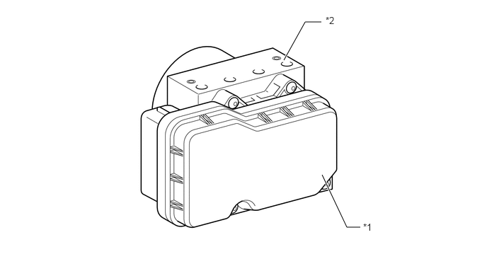
The brake actuator assembly consists of the actuator portion and skid control ECU.
4.177,0.885 4.49,0.323
4.49,0.323 4.729,0.323
true
4.74,2.573 5.104,3.344
5.104,3.344 5.302,3.344
true
5.344,3.26 5.656,3.417
0.313,0.156
10
false
*1
4.792,0.219 5.104,0.375
0.313,0.156
10
false
*2
| *1 | Skid Control ECU | *2 | Actuator Portion |
b.
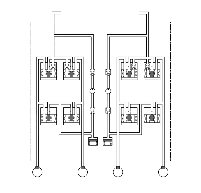
The actuator portion regulates the hydraulic brake pressure to each wheel cylinder.
c.
The brake actuator assembly is constructed with the following hydraulic circuit:
1.646,2.875 2,3.073
0.354,0.198
10
*1
2.458,2.875 2.813,3.073
0.354,0.198
10
*1
1.646,4.469 2,4.667
0.354,0.198
10
*2
3.031,3.146 3.385,3.344
0.354,0.198
10
*3
3.781,5.188 4.135,5.385
0.354,0.198
10
*4
2.229,0.375 2.583,0.573
0.354,0.198
10
*a
1.26,6.313 1.615,6.51
0.354,0.198
10
*5
2.885,6.313 3.24,6.51
0.354,0.198
10
*6
4.135,6.313 4.49,6.51
0.354,0.198
10
*7
5.75,6.313 6.104,6.51
0.354,0.198
10
*8
3.969,3.146 4.323,3.344
0.354,0.198
10
*3
3.24,5.188 3.594,5.385
0.354,0.198
10
*4
5.344,4.469 5.698,4.667
0.354,0.198
10
*2
4.521,4.469 4.875,4.667
0.354,0.198
10
*2
2.458,4.469 2.813,4.667
0.354,0.198
10
*2
4.521,2.875 4.875,3.073
0.354,0.198
10
*1
5.344,2.875 5.698,3.073
0.354,0.198
10
*1
4.75,0.365 5.104,0.563
0.354,0.198
10
*a
| *1 | Pressure Holding Solenoid Valve | *2 | Pressure Reduction Solenoid Valve |
| *3 | Pump Motor | *4 | Reservoir |
| *5 | Front Wheel Cylinder LH | *6 | Rear Wheel Cylinder RH |
| *7 | Rear Wheel Cylinder LH | *8 | Front Wheel Cylinder RH |
| *a | From Master Cylinder | - | - |
OPERATION
a.
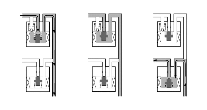
Based on the signals received from the 4 speed sensors, the skid control ECU calculates the speed of each wheel, and checks wheel slipping conditions. In accordance with the slipping condition, the skid control ECU controls each solenoid valve in the brake actuator assembly in order to adjust the fluid pressure of each wheel cylinder in the following 3 modes: pressure increase, pressure holding, and pressure reduction modes.
2.823,2.844 3,2.844
3,2.844 3.583,2.51
true
2.802,0.615 2.99,0.615
2.99,0.615 3.583,0.917
true
6.333,3.385 6.49,3.563
0.156,0.177
10
false
*e
5.813,0.156 5.969,0.333
0.156,0.177
10
false
*c
3.521,0.156 3.677,0.333
0.156,0.177
10
false
*b
2.635,2.75 2.792,2.927
0.156,0.177
10
false
*4
1.24,3.25 1.396,3.427
0.156,0.177
10
false
*2
1.24,1.677 1.396,1.854
0.156,0.177
10
false
*1
2.625,0.531 2.781,0.708
0.156,0.177
10
false
*3
1.24,0.156 1.396,0.333
0.156,0.177
10
false
*a
1.802,3.385 1.958,3.563
0.156,0.177
10
false
*d
| *1 | Pressure Holding Solenoid Valve | *2 | Pressure Reduction Solenoid Valve |
| *3 | Port A | *4 | Port B |
| *a | Normal Braking or Pressure Increase Mode | *b | Pressure Holding Mode |
| *c | Pressure Reduction Mode | *d | To Wheel Cylinder |
| *e | From Wheel Cylinder | - | - |
| Pressure Mode | Increase Mode | Holding Mode | Reduction Mode |
|---|---|---|---|
| Pressure Holding Solenoid Valve (Port A) | Off (Open) | On (Closed) | ← |
| Pressure Reduction Solenoid Valve (Port B) | Off (Closed) | ← | On (Open) |
| Wheel Cylinder Pressure | Increases | Holds | Reduces |