HEATING / AIR CONDITIONING AIR CONDITIONING SYSTEM CONTROL AIR CONDITIONING CONTROL
FUNCTION OF MAIN COMPONENTS
The main components of the air conditioning system have the following functions:
| Component | Function |
|---|---|
|
*1: Except models with manual air conditioning system for 1NZ-FE engine or 2NZ-FE engine *2: Models with automatic air conditioning system *3: Models with 1NZ-FE engine or 2NZ-FE engine *4: Models with 1NR-FE engine or 2NR-FE engine |
|
| Air Conditioning Control Assembly | Allows operation and adjustment of the air conditioning system via switches. |
| Air Conditioning Amplifier Assembly | Transmits and receives data to and from the switches and sensors, and controls the air conditioning system. |
| Cooler Compressor Assembly | A compact and lightweight 10-cylinder swash plate type cooler compressor assembly is used. |
| Blower Motor with Fan Sub-assembly | The fan blades are thin, and improve air flow inside the blower fan, contributing to the reduction of noise. |
| Cooler Condenser Assembly | A Multi-Flow (MF)-IV sub-cool condenser is used to improve heat exchange efficiency. |
| Heater Radiator Unit Sub-assembly | A Straight Flow Aluminum (SFA)-II heater radiator is used for compactness and high performance. |
| No. 1 Cooler Evaporator Sub-assembly | A Revolutionary super-Slim structure (RS) evaporator*3 or Beneficial Refrigerant Stream (BRS) evaporator*4 is used for compactness. |
| No. 1 Cooler Thermistor | Detects the temperature of the cool air past the No. 1 cooler evaporator sub-assembly and transmits the data to the air conditioning amplifier assembly. |
| Ambient Temperature Sensor (Thermistor Assembly)*1 | Detects ambient temperature and outputs it to the air conditioning amplifier assembly. |
| Cooler (Room Temp. Sensor) Thermistor*2 | Detects room temperature and outputs it to the air conditioning amplifier assembly. |
| Cooler (Solar Sensor) Thermistor*2 | Detects the changes in the amount of solar energy and outputs them to the air conditioning amplifier assembly. |
| Air Inlet Servo Motor (Recirculation Damper Servo Sub-assembly)*2 | Receives the input of the operation signals from the fresh-air/recirculation selector switch via the air conditioning amplifier assembly, operates the motor, and opens and closes the fresh-air/ recirculation damper. |
| Air Outlet Servo Motor (Mode Damper Servo Sub-assembly)*2 | Receives the input of the operation signals from the mode selector switch via the air conditioning amplifier assembly, operates the motor, and opens and closes the mode damper. |
| Air Mix Servo Motor (Air Mix Damper Servo Sub-assembly)*2 | Receives the input of temperature setting dial signals via the air conditioning amplifier assembly, operates the motor, and opens and closes the air mix damper. |
| Clean Air Filter | Removes particles to provide a comfortable interior space. |
| No. 1 Pressure Switch*3/Air Conditioning Pressure Sensor*4 | Detects the refrigerant pressure and sends the data to the air conditioning amplifier assembly. |
| ECM | Regulates the engine speed and then turns on or off the GM CLT relay, in response to signals from the air conditioning amplifier assembly. |
SYSTEM CONTROL
The automatic air conditioning system uses the following controls:
| Control | Outline | Air Conditioning Type | ||
|---|---|---|---|---|
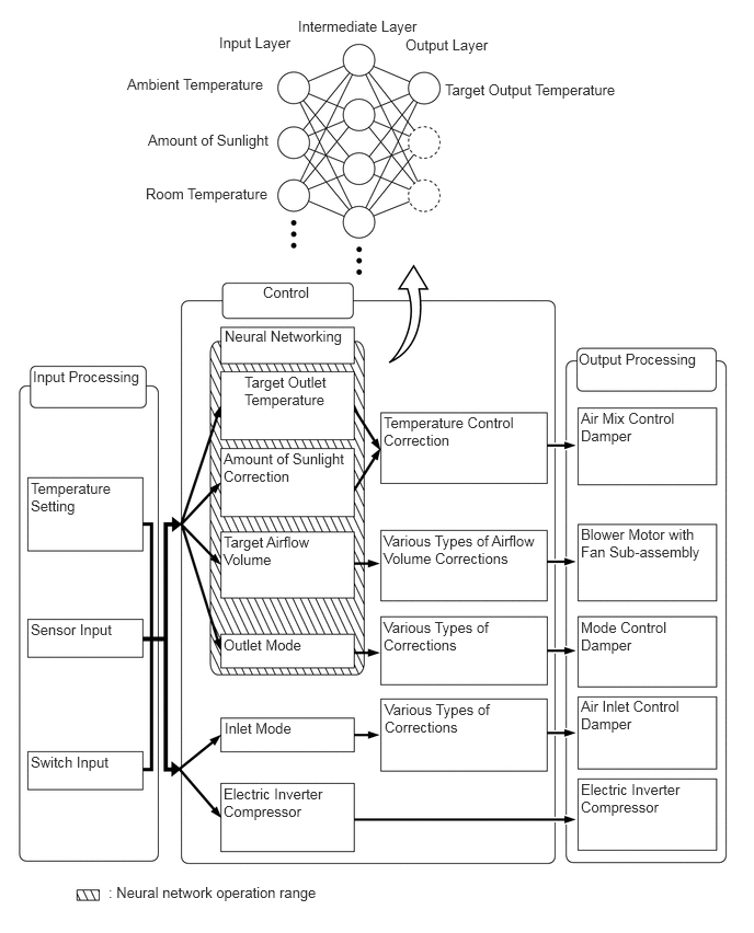
| Neural Network Control | This control is capable of effecting complex control by artificially simulating the information processing method of the nervous system of living organisms in order to establish a complex input or output relationship that is similar to a human brain. | ○ | - | |
| Outlet Air Temperature Control | After receiving the signals from the sensors and the temperature control switching setting, then it uses a prescribed formula to calculate the required outlet air temperature, and regulate the servomotors and the blower motor with fan sub-assembly. This outlet temperature is required in order to maintain the set temperature in a stable manner. | ○ | - | |
| Blower Control | Manual Control | Sets the blower speed according to operation of the blower switch. | ○ | ○ |
| Automatic Control | This function controls the operation of the blower motor with fan sub-assembly in accordance with the signals from the No. 1 cooler thermistor, the cooler (room temp. sensor) thermistor and the cooler (solar sensor) thermistor. In addition, it protects the blower motor control from the sudden drive current that occurs when the blower motor with fan sub-assembly is activated. | ○ | - | |
| Air Outlet Control | Manual Control | Changes the air outlet in accordance with the selected position of the mode select switch. | ○ | ○ |
| Automatic Control | Controls the air outlet mode to switch to FACE and BI-LEVEL in accordance with the required outlet air temperature when the AUTO switch has been turned ON. | ○ | - | |
| Compressor Control | When the AUTO switch is turned ON, the MG CLT relay is activated automatically to engage the compressor. | ○ | - | |
| Diagnosis | A Diagnostic Trouble Code (DTC) is stored in memory when the air conditioning amplifier assembly detects a problem with the air conditioning system. | ○ | - | |
Neural Network Control
Previously, in automatic air conditioning systems without neural network control, the air conditioning amplifier assembly determined the required outlet air temperature and blower air volume in accordance with the calculation formula that has been obtained based on information received from the sensors. However, because the senses of a person are rather complex, a given temperature is sensed differently, depending on the environment in which the person is situated. For example, a given amount of solar radiation can feel comfortably warm in a cold climate, or extremely uncomfortable in a hot climate. Therefore, as a technique for effecting a higher level of control, a neural network has been adopted in the automatic air conditioning system. With this technique, the data that has been collected under varying environmental conditions is stored in the air conditioning amplifier assembly. The air conditioning amplifier assembly can then effect control to provide enhanced air conditioning comfort.
The neural network control consists of neurons in the input layer, intermediate layer, and output layer. The input layer neurons process the input data of the ambient temperature, the amount of sunlight, and the room temperature based on the outputs of the switches and sensors, and output them to the intermediate layer neurons. Based on this data, the intermediate layer neurons adjust the strength of the links among the neurons. The sum of these is then calculated by the output layer neurons in the form of the required outlet temperature, solar correction, target airflow volume, and outlet mode control volume. Accordingly, the air conditioning amplifier assembly controls the servo motors and blower motor with fan sub-assembly in accordance with the control volumes that have been calculated by the neural network control.
DIAGNOSIS
The air conditioning amplifier assembly has a diagnosis function. It stores any operation failures in the memory in the form of Diagnostic Trouble Codes (DTCs). For details, refer to the Repair Manual.