NM30M0E
_58
Vehicle Interior
_018278
HEATING / AIR CONDITIONING
_0090351
AIR CONDITIONING SYSTEM
DE
DETAILS
F
HEATING / AIR CONDITIONING AIR CONDITIONING SYSTEM DETAILS COMPRESSOR WITH PULLEY
CONSTRUCTION
a.
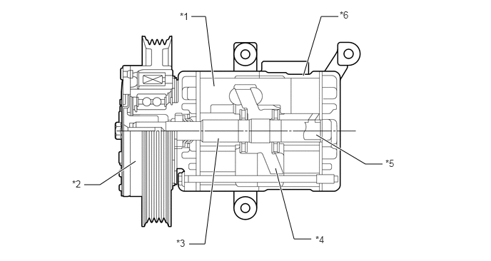
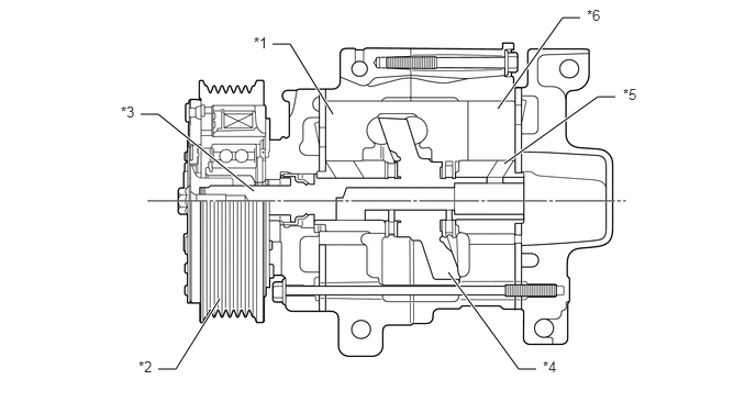
A compact and lightweight 10-cylinder swash plate type 10SE13C*1 or 10SRE11C*2 cooler compressor assembly is used.
- HINT:
-
*1: Models with 1NZ-FE engine or 2NZ-FE engine
-
*2: Models with 1NR-FE engine or 2NR-FE engine
10SE13C
3.125,1.26 3,0.24
3,0.24 2.792,0.24
true
4.427,1.104 4.688,0.24
4.688,0.24 4.938,0.24
true
4.615,1.969 5.333,2.396
5.333,2.396 5.583,2.396
true
4.021,2.458 4.292,3.49
4.292,3.49 4.542,3.49
true
3.188,2.021 2.99,3.563
2.99,3.563 2.76,3.563
true
1.979,2.354 1.458,2.698
1.458,2.698 1.229,2.698
true
2.625,0.156 2.938,0.313
0.313,0.156
10
false
*1
1.052,2.604 1.365,2.76
0.313,0.156
10
false
*2
2.573,3.469 2.885,3.625
0.313,0.156
10
false
*3
4.604,3.417 4.917,3.573
0.313,0.156
10
false
*4
5.625,2.302 5.938,2.458
0.313,0.156
10
false
*5
4.958,0.135 5.271,0.292
0.313,0.156
10
false
*6
| *1 | Piston | *2 | Pulley |
| *3 | Shaft | *4 | Swash Plate |
| *5 | Rotary Valve | *6 | Cylinder |
10SRE11C
4.719,1.031 5.333,0.167
5.333,0.167 5.5,0.167
true
4.781,1.552 5.667,0.917
5.667,0.917 5.833,0.917
true
4.25,2.583 4.917,3.5
4.917,3.5 5.083,3.5
true
2.083,2.833 1.667,3.5
1.667,3.5 1.5,3.5
true
2.406,1.813 1.5,1.083
1.5,1.083 1.333,1.083
true
3.156,1.083 2.75,0.417
2.75,0.417 2.583,0.417
true
5.563,0.063 5.875,0.26
0.313,0.198
10
false
*6
5.906,0.813 6.219,1.01
0.313,0.198
10
false
*5
5.146,3.396 5.458,3.594
0.313,0.198
10
false
*4
1.313,3.396 1.625,3.594
0.313,0.198
10
false
*2
1.146,0.979 1.458,1.177
0.313,0.198
10
false
*3
2.406,0.323 2.719,0.521
0.313,0.198
10
false
*1
| *1 | Piston | *2 | Pulley |
| *3 | Shaft | *4 | Swash Plate |
| *5 | Rotary Valve | *6 | Cylinder |
b.
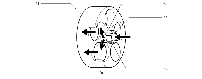
A rotary valve capable of drawing refrigerant into the cylinder has been provided.
c.
A hollow shaft is used in the valve so as to allow refrigerant to be sucked into the compressing section of the cylinder through the hollow section. Holes individually arranged on the shaft and cylinder are designed to align during the rotation of the shaft. When the holes are aligned, refrigerant is sucked into the compressing section.
1.448,0.125 2.51,0.125
2.51,0.125 2.948,0.552
true
5.74,0.135 4.313,0.135
4.313,0.135 3.719,1.281
true
5.76,0.625 4.563,0.625
4.563,0.625 4.073,1.177
true
5.76,2.448 4.479,2.448
4.479,2.448 3.948,1.49
true
1.271,0.052 1.604,0.302
0.333,0.25
10
*1
5.813,2.365 6.344,2.615
0.531,0.25
10
*2
5.813,0.552 6.146,0.802
0.333,0.25
10
*3
3.531,2.49 3.865,2.708
0.333,0.219
10
*a
5.792,0.073 6.323,0.323
0.531,0.25
10
*4
| *1 | Cylinder | *2 | Cylinder Suction Passage |
| *3 | Shaft | *4 | Rotary Valve Suction Port |
| *a | The position where the rotary valve suction port and cylinder suction passage become aligned. | - | - |

|
Refrigerant Flow | - | - |