Home › Brake › BRAKE CONTROL / DYNAMIC CONTROL SYSTEMS › BRAKE CONTROL SYSTEM › 2016.04–2017.10
NM30M0E _54 Brake _018312 BRAKE CONTROL / DYNAMIC CONTROL SYSTEMS _0090428 BRAKE CONTROL SYSTEM DE DETAILS F

BRAKE CONTROL / DYNAMIC CONTROL SYSTEMS  BRAKE CONTROL SYSTEM  DETAILS  BRAKE CONTROL  


OPERATION


a.

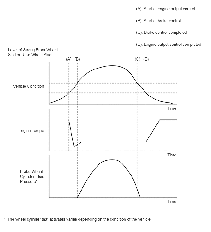
Engine Output Control during TRC or VSC Operation

i.

During the TRC or VSC operation, the skid control ECU outputs the engine output control signal to the ECM. Upon receiving this signal, the ECM inhibits the engine output.
X100710E01
4.625,0.208 6.802,0.5 2.177,0.292 10 (A): Start of engine output control 4.625,0.615 6.208,0.938 1.583,0.323 10 (B): Start of brake control 4.625,1.01 6.417,1.354 1.792,0.344 10 (C): Brake control completed 4.625,1.417 7,1.75 2.375,0.333 10 (D): Engine output control completed 0.271,1.604 2.01,2.042 1.74,0.438 10 Level of Strong Front Wheel Skid or Rear Wheel Skid 2.24,1.917 2.552,2.198 0.313,0.281 10 (A) 2.531,1.917 2.854,2.198 0.323,0.281 10 (B) 4.573,1.917 4.844,2.198 0.271,0.281 10 (C) 4.865,1.917 5.177,2.177 0.313,0.26 10 (D) 0.448,2.833 1.573,3.198 1.125,0.365 10 Vehicle Condition 0.625,4.333 1.573,4.688 0.948,0.354 10 Engine Torque 0.677,5.729 1.573,6.313 0.896,0.583 10 Brake Wheel Cylinder Fluid Pressure* 5.688,3.583 6.021,3.927 0.333,0.344 10 Time 5.688,5.167 6.021,5.51 0.333,0.344 10 Time 5.688,6.74 6.021,7.083 0.333,0.344 10 Time 0.125,7.344 5.323,7.719 5.198,0.375 10 *: The wheel cylinder that activates varies depending on the condition of the vehicle


b.

ABS with EBD

i.

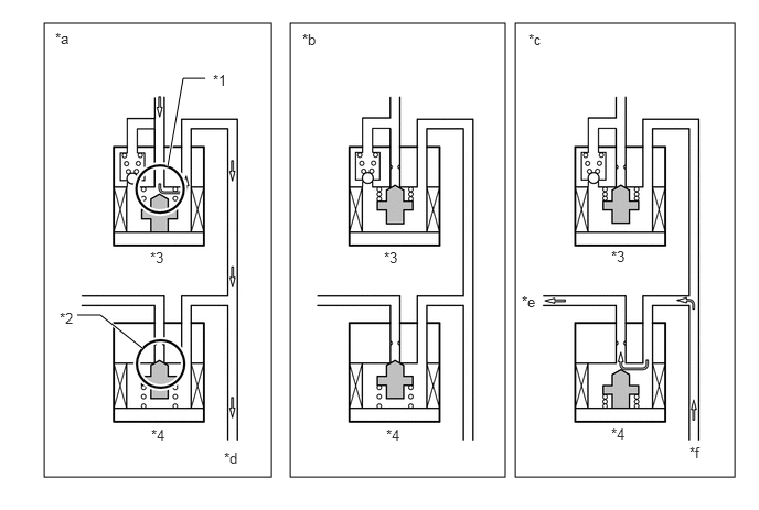
Based on the signals received from the 4 speed sensors, the skid control ECU calculates each wheel speed and deceleration, and checks wheel slipping conditions. According to the slipping condition, the skid control ECU controls the pressure holding valve and pressure reduction valve in order to adjust the fluid pressure of each wheel cylinder in the following 3 modes: pressure reduction, pressure holding and pressure increase modes.
X110377C03
0.417,0.219 2.563,4.51 2.146,4.292 2.74,0.219 4.771,4.51 2.031,4.292 4.865,0.219 6.938,4.51 2.073,4.292 1.583,1.573 1.729,0.74 1.729,0.74 1.938,0.74 true 0.729,2.979 0.948,2.979 0.948,2.979 1.344,3.292 true 2.01,0.677 2.323,0.833 0.313,0.156 10 *1 0.563,2.927 0.875,3.083 0.313,0.156 10 *2 1.417,2.354 1.729,2.51 0.313,0.156 10 *3 1.427,4.031 1.74,4.188 0.313,0.156 10 *4 0.521,0.281 0.833,0.438 0.313,0.156 10 *a 2.854,0.292 3.167,0.448 0.313,0.156 10 *b 4.99,0.292 5.302,0.448 0.313,0.156 10 *c 2.115,4.25 2.427,4.406 0.313,0.156 10 *d 4.927,2.771 5.24,2.927 0.313,0.156 10 *e 3.625,2.354 3.938,2.552 0.313,0.198 10 *3 5.771,2.344 6.083,2.542 0.313,0.198 10 *3 3.646,4.031 3.958,4.229 0.313,0.198 10 *4 5.771,4.021 6.083,4.219 0.313,0.198 10 *4 6.51,4.198 6.823,4.354 0.313,0.156 10 *f
*1 Port A *2 Port B
*3 Pressure Holding Valve *4 Pressure Reduction Valve
*a Increase Mode *b Holding Mode
*c Reduction Mode *d to Wheel Cylinder
*e to Reservoir and Pump *f from Wheel Cylinder


Not Activated Normal Braking - -
Activated Increase Mode Holding Mode Reduction Mode
Pressure Holding Valve (Port A) OFF (Open) ON (Close) ON (Close)
Pressure Reduction Valve (Port B) OFF (Close) OFF (Close) ON (Open)
Wheel Cylinder Pressure Increased Held Reduced


c.

Brake Assist (Electrical Type Brake Assist)

i.

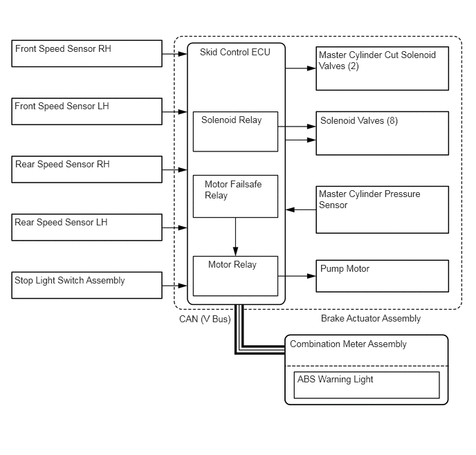
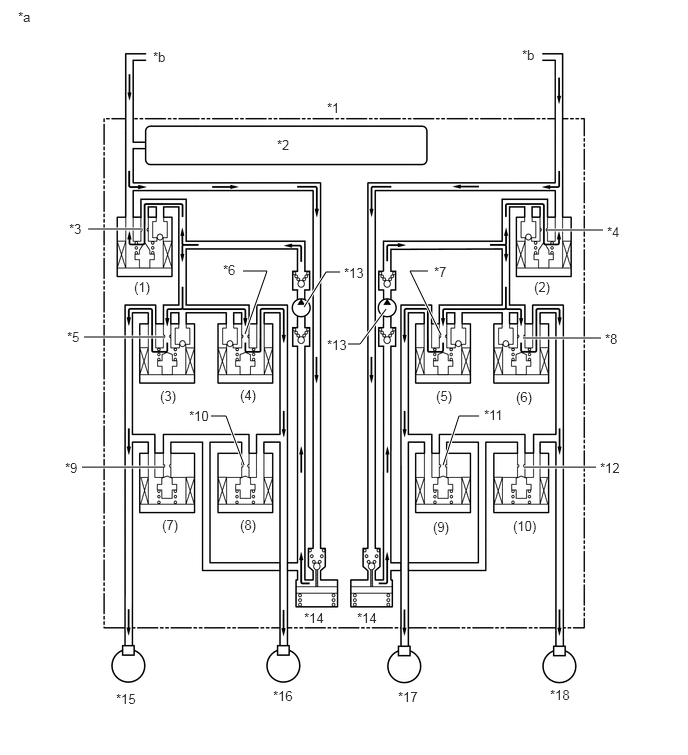
In the event of emergency braking, the skid control ECU determines the driver's intentions based on the speed of the pressure increase in the master cylinder detected by the master cylinder pressure sensor signal. If the skid control ECU judges the need for additional brake assist, pressure to supplement the amount provided by the master cylinder is generated by the pump in the brake actuator and directed to each wheel cylinder.
X131907E01
0.229,0.646 1.802,0.885 1.573,0.24 10 false Front Speed Sensor RH 0.219,1.51 1.688,1.74 1.469,0.229 10 false Front Speed Sensor LH 0.229,2.385 1.708,2.646 1.479,0.26 10 false Rear Speed Sensor RH 0.219,3.26 1.688,3.469 1.469,0.208 10 false Rear Speed Sensor LH 0.219,4.135 2.031,4.333 1.813,0.198 10 false Stop Light Switch Assembly 3.01,0.698 4.156,0.917 1.146,0.219 10 false Skid Control ECU 3.031,1.719 4,1.958 0.969,0.24 10 false Solenoid Relay 3.083,2.688 3.99,3.073 0.906,0.385 10 false Motor Failsafe Relay 3.135,3.896 3.979,4.219 0.844,0.323 10 false Motor Relay 4.802,0.74 6.635,1.156 1.833,0.417 10 false Master Cylinder Cut Solenoid Valves (2) 4.823,1.729 6.063,2.063 1.24,0.333 10 false Solenoid Valves (8) 4.802,2.833 6.458,3.292 1.656,0.458 10 false Master Cylinder Pressure Sensor 4.823,3.958 5.646,4.219 0.823,0.26 10 false Pump Motor 4.833,4.708 6.49,4.969 1.656,0.26 10 false Brake Actuator Assembly 2.698,4.719 3.573,4.979 0.875,0.26 10 false CAN (V Bus) 4.365,5.094 6.271,5.396 1.906,0.302 10 false Combination Meter Assembly 4.479,5.625 5.771,5.875 1.292,0.25 10 false ABS Warning Light

X100721C02
0.917,2.385 1.479,2.385 true 5.698,2.396 6.281,2.396 true 5.448,3.521 6.26,3.521 true 5.458,4.865 6.208,4.865 true 4.594,3.49 4.271,2.823 4.271,2.823 4.458,2.823 true 3.167,3.198 3.396,2.833 3.396,2.833 3.542,2.833 true 2.531,2.823 2.781,2.823 2.781,2.823 2.552,3.479 true 0.875,3.51 1.708,3.51 true 0.854,4.865 1.698,4.865 true 2.198,4.333 2.354,4.333 2.354,4.333 2.542,4.844 true 4.021,3.219 3.75,3.583 3.75,3.583 3.625,3.583 true 4.99,4.333 4.781,4.333 4.781,4.333 4.615,4.844 true 1.594,0.51 1.906,0.708 0.313,0.198 10 *b 5.438,0.49 5.75,0.688 0.313,0.198 10 *b 3.406,1.042 3.719,1.24 0.313,0.198 10 *1 2.885,1.427 3.198,1.625 0.313,0.198 10 *2 0.719,2.302 1.031,2.5 0.313,0.198 10 *3 0.698,3.427 1.01,3.625 0.313,0.198 10 *5 2.323,2.729 2.635,2.927 0.313,0.198 10 *6 1.396,2.906 1.656,3.135 0.26,0.229 10 (1) 4.521,2.75 4.833,2.948 0.313,0.198 10 *7 5.563,2.906 5.844,3.094 0.281,0.188 10 (2) 6.323,2.333 6.635,2.531 0.313,0.198 10 *4 6.302,3.448 6.615,3.646 0.313,0.198 10 *8 5.375,4.052 5.635,4.313 0.26,0.26 10 (6) 4.542,4.042 4.813,4.323 0.271,0.281 10 (5) 3.406,3.51 3.677,3.74 0.271,0.229 10 *13 2.5,4.031 2.844,4.281 0.344,0.25 10 (4) 1.667,4.042 1.969,4.313 0.302,0.271 10 (3) 0.677,4.792 0.99,4.99 0.313,0.198 10 *9 1.688,5.385 1.969,5.615 0.281,0.229 10 (7) 2.5,5.385 2.76,5.604 0.26,0.219 10 (8) 1.969,4.25 2.198,4.479 0.229,0.229 10 *10 4.51,5.406 4.792,5.667 0.281,0.26 10 (9) 5.344,5.396 5.74,5.646 0.396,0.25 10 (10) 6.25,4.792 6.646,5.073 0.396,0.281 10 *12 5.042,4.24 5.281,4.448 0.24,0.208 10 *11 3.167,6.354 3.427,6.552 0.26,0.198 10 *14 1.208,7.198 1.51,7.427 0.302,0.229 10 *15 2.844,7.167 3.135,7.375 0.292,0.208 10 *16 4.146,7.177 4.427,7.396 0.281,0.219 10 *17 5.729,7.156 6.042,7.385 0.313,0.229 10 *18 0.188,0.094 0.5,0.292 0.313,0.198 10 *a 3.583,2.76 3.854,2.99 0.271,0.229 10 *13 3.719,6.354 3.979,6.552 0.26,0.198 10 *14
*1 Brake Actuator Assembly *2 Master Cylinder Pressure Sensor
*3 Port (A) *4 Port (B)
*5 Port (C) *6 Port (D)
*7 Port (E) *8 Port (F)
*9 Port (G) *10 Port (H)
*11 Port (I) *12 Port (J)
*13 Pump *14 Reservoir
*15 Front Wheel Cylinder RH *16 Rear Wheel Cylinder LH
*17 Rear Wheel Cylinder RH *18 Front Wheel Cylinder LH
*a Brake Assist Operation *b From Master Cylinder


ii.

Each valve operates as shown below:

Item Port Not Activated Activated

*: Hydraulic pressure is controlled by continuously cycling the solenoid valves between open and closed, according to the operating conditions.

Master Cylinder Cut Solenoid Valve (1) (A) OFF (Open) ON*
(2) (B) OFF (Open) ON*
Pressure Holding Solenoid Valve (3) (C) OFF (Open) OFF (Open)
(4) (D) OFF (Open) OFF (Open)
(5) (E) OFF (Open) OFF (Open)
(6) (F) OFF (Open) OFF (Open)
Pressure Reduction Solenoid Valve (7) (G) OFF (Closed) OFF (Closed)
(8) (H) OFF (Closed) OFF (Closed)
(9) (I) OFF (Closed) OFF (Closed)
(10) (J) OFF (Closed) OFF (Closed)
Pump OFF ON


d.

TRC

i.

The fluid pressure generated by the pump is regulated by the master cylinder cut solenoid valve to the required pressure. Thus, the wheel cylinders of the drive wheels are controlled in the following 3 modes: pressure reduction, pressure holding, and pressure increase modes to control the slippage of the drive wheels. The diagram below shows the hydraulic circuit in pressure increase mode when the TRC is activated. Each pressure holding solenoid valve and the pressure reduction solenoid valve is turned on/off according to the ABS with EBD operation pattern.
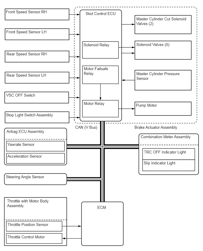
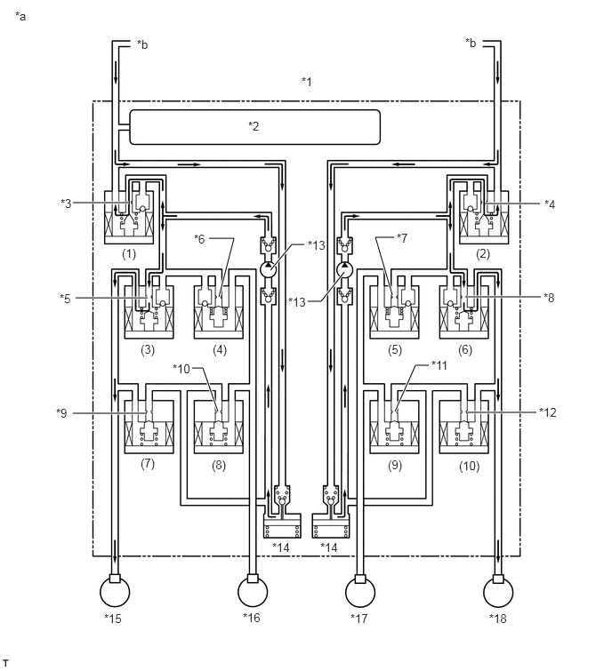
X131908E01
0.208,0.333 1.75,0.625 1.542,0.292 10 false Front Speed Sensor RH 0.219,1.042 1.708,1.302 1.49,0.26 10 false Front Speed Sensor LH 0.229,1.823 1.729,2.052 1.5,0.229 10 false Rear Speed Sensor RH 0.229,2.573 1.719,2.792 1.49,0.219 10 false Rear Speed Sensor LH 0.219,3.281 1.313,3.49 1.094,0.208 10 false VSC OFF Switch 0.208,3.979 1.969,4.24 1.76,0.26 10 false Stop Light Switch Assembly 3.021,0.396 4.198,0.667 1.177,0.271 10 false Skid Control ECU 2.948,1.5 3.917,1.771 0.969,0.271 10 false Solenoid Relay 2.958,2.344 3.917,2.802 0.958,0.458 10 false Motor Failsafe Relay 2.958,3.573 3.802,3.813 0.844,0.24 10 false Motor Relay 4.813,0.583 6.635,0.99 1.823,0.406 10 false Master Cylinder Cut Solenoid Valves (2) 4.813,1.49 6.052,1.823 1.24,0.333 10 false Solenoid Valves (8) 4.813,2.521 6.417,3 1.604,0.479 10 false Master Cylinder Pressure Sensor 4.802,3.635 5.615,3.896 0.813,0.26 10 false Pump Motor 2.656,4.417 3.563,4.667 0.906,0.25 10 false CAN (V Bus) 4.75,4.417 6.406,4.677 1.656,0.26 10 false Brake Actuator Assembly 0.229,4.563 1.646,4.802 1.417,0.24 10 false Airbag ECU Assembly 0.26,5.021 1.323,5.229 1.063,0.208 10 false Yawrate Sensor 0.26,5.438 1.563,5.719 1.302,0.281 10 false Acceleration Sensor 4.969,4.75 6.802,4.969 1.833,0.219 10 false Combination Meter Assembly 5.083,5.292 6.656,5.552 1.573,0.26 10 false TRC OFF Indicator Light 5.073,5.677 6.229,5.948 1.156,0.271 10 false Slip Indicator Light 0.25,7.021 1.76,7.563 1.51,0.542 10 false Throttle with Motor Body Assembly 3.438,7.25 3.896,7.448 0.458,0.198 10 false ECM 0.26,8.292 1.625,8.49 1.365,0.198 10 false Throttle Control Motor 0.26,7.854 1.833,8.083 1.573,0.229 10 false Throttle Position Sensor 0.208,6.167 3.417,6.365 3.208,0.198 10 false Steering Angle Sensor

X100723C02
5.677,2.385 6.323,2.385 true 5.448,3.479 6.333,3.479 true 5.479,4.833 6.281,4.833 true 3.167,3.167 3.417,2.865 3.417,2.865 3.563,2.865 true 2.25,4.313 2.375,4.313 2.375,4.313 2.552,4.823 true 0.854,4.844 1.708,4.844 true 0.885,3.49 1.729,3.49 true 4.594,3.458 4.396,2.781 4.396,2.781 4.615,2.781 true 2.563,3.479 2.74,2.792 2.74,2.792 2.448,2.792 true 0.854,2.375 1.51,2.375 true 4.031,3.188 3.76,3.531 3.76,3.531 3.604,3.531 true 5.021,4.281 4.865,4.281 4.865,4.281 4.625,4.823 true 0.177,0.104 0.49,0.302 0.313,0.198 10 *a 1.604,0.438 1.917,0.635 0.313,0.198 10 *b 5.448,0.417 5.76,0.615 0.313,0.198 10 *b 3.531,0.875 3.844,1.073 0.313,0.198 10 *1 2.906,1.396 3.219,1.594 0.313,0.198 10 *2 0.708,2.302 1.021,2.5 0.313,0.198 10 *3 0.698,3.417 1.01,3.615 0.313,0.198 10 *5 1.427,2.885 1.708,3.146 0.281,0.26 10 (1) 2.271,2.719 2.583,2.917 0.313,0.198 10 *6 1.646,4.01 1.938,4.24 0.292,0.229 10 (3) 2.49,4.01 2.771,4.25 0.281,0.24 10 (4) 0.656,4.76 0.969,4.958 0.313,0.198 10 *9 1.646,5.344 1.896,5.604 0.25,0.26 10 (7) 2.479,5.365 2.729,5.594 0.25,0.229 10 (8) 2.021,4.24 2.281,4.458 0.26,0.219 10 *10 3.604,2.792 3.875,3.042 0.271,0.25 10 *13 4.646,2.708 4.917,2.896 0.271,0.188 10 *7 6.375,2.313 6.688,2.51 0.313,0.198 10 *4 5.573,2.885 5.854,3.094 0.281,0.208 10 (2) 6.365,3.406 6.677,3.604 0.313,0.198 10 *8 6.313,4.75 6.604,4.99 0.292,0.24 10 *12 4.542,5.365 4.802,5.563 0.26,0.198 10 (9) 5.375,5.375 5.708,5.625 0.333,0.25 10 (10) 5.052,4.198 5.292,4.406 0.24,0.208 10 *11 3.188,6.333 3.5,6.563 0.313,0.229 10 *14 1.219,7.167 1.531,7.417 0.313,0.25 10 *15 2.844,7.156 3.156,7.396 0.313,0.24 10 *16 4.104,7.167 4.417,7.438 0.313,0.271 10 *17 5.729,7.167 6.073,7.448 0.344,0.281 10 *18 4.542,4.01 4.823,4.25 0.281,0.24 10 (5) 5.365,4.01 5.677,4.219 0.313,0.208 10 (6) 3.75,6.333 4.063,6.563 0.313,0.229 10 *14 3.375,3.458 3.646,3.708 0.271,0.25 10 *13
*1 Brake Actuator Assembly *2 Master Cylinder Pressure Sensor
*3 Port (A) *4 Port (B)
*5 Port (C) *6 Port (D)
*7 Port (E) *8 Port (F)
*9 Port (G) *10 Port (H)
*11 Port (I) *12 Port (J)
*13 Pump *14 Reservoir
*15 Front Wheel Cylinder RH *16 Rear Wheel Cylinder LH
*17 Rear Wheel Cylinder RH *18 Front Wheel Cylinder LH
*a TRC Operation *b From Master Cylinder


Item Port Not Activated Activated
Increase Mode Holding Mode Reduction Mode

*: Hydraulic pressure is controlled by continuously cycling the solenoid valves between open and closed, according to the operating conditions.

Master Cylinder Cut Solenoid Valve (1) (A) OFF (Open) ON* ON* ON*
(2) (B) OFF (Open) ON* ON* ON*
Front Brake Pressure Holding Solenoid Valve (3) (C) OFF (Open) OFF (Open) OFF (Open) ON (Closed)
(6) (F) OFF (Open) OFF (Open) OFF (Open) ON (Closed)
Pressure Reduction Solenoid Valve (7) (G) OFF (Closed) OFF (Closed) OFF (Closed) ON (Open)
(10) (J) OFF (Closed) OFF (Closed) OFF (Closed) ON (Open)
Brake Wheel Cylinder Pressure Right - - Increase Hold Reduce
Left - - Increase Hold Reduce
Rear Brake Pressure Holding Solenoid Valve (4) (D) OFF (Open) ON (Closed) ON (Closed) ON (Closed)
(5) (E) OFF (Open) ON (Closed) ON (Closed) ON (Closed)
Pressure Reduction Solenoid Valve (8) (H) OFF (Closed) OFF (Closed) OFF (Closed) OFF (Closed)
(9) (I) OFF (Closed) OFF (Closed) OFF (Closed) OFF (Closed)
Brake Wheel Cylinder Pressure Right - - - - -
Left - - - - -
Pump OFF ON ON ON


e.

VSC

i.

The VSC, by the way of solenoid valves, controls the fluid pressure that is generated by the pump and applies it to the brake wheel cylinder of each wheel in the following 3 modes: pressure reduction, pressure holding, and pressure increase modes. As a result, the tendency of front wheel skid or rear wheel skid is controlled.
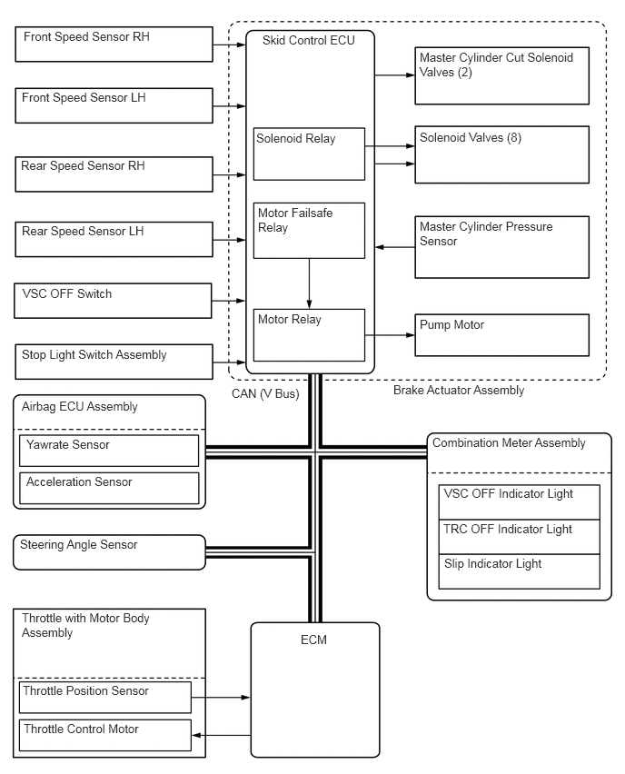
X131909E01
0.271,0.333 1.792,0.583 1.521,0.25 10 false Front Speed Sensor RH 0.25,1.031 1.781,1.24 1.531,0.208 10 false Front Speed Sensor LH 0.24,1.813 1.729,2.073 1.49,0.26 10 false Rear Speed Sensor RH 0.25,2.563 1.75,2.813 1.5,0.25 10 false Rear Speed Sensor LH 0.26,3.281 1.406,3.49 1.146,0.208 10 false VSC OFF Switch 0.25,3.979 2.021,4.229 1.771,0.25 10 false Stop Light Switch Assembly 3.01,0.375 4.177,0.688 1.167,0.313 10 false Skid Control ECU 2.938,1.5 3.938,1.792 1,0.292 10 false Solenoid Relay 2.958,2.354 3.906,2.833 0.948,0.479 10 false Motor Failsafe Relay 2.958,3.573 3.75,3.844 0.792,0.271 10 false Motor Relay 4.813,0.573 6.635,1.01 1.823,0.438 10 false Master Cylinder Cut Solenoid Valves (2) 4.813,1.49 6.052,1.802 1.24,0.313 10 false Solenoid Valves (8) 4.813,2.51 6.385,2.927 1.573,0.417 10 false Master Cylinder Pressure Sensor 4.813,3.635 5.625,3.906 0.813,0.271 10 false Pump Motor 2.656,4.427 3.51,4.688 0.854,0.26 10 false CAN (V Bus) 4.51,4.385 6.167,4.656 1.656,0.271 10 false Brake Actuator Assembly 0.229,6.156 1.698,6.427 1.469,0.271 10 false Steering Angle Sensor 0.25,4.573 1.74,4.865 1.49,0.292 10 false Airbag ECU Assembly 0.302,5.01 1.375,5.25 1.073,0.24 10 false Yawrate Sensor 0.302,5.438 1.625,5.667 1.323,0.229 10 false Acceleration Sensor 4.958,4.99 6.781,5.281 1.823,0.292 10 false Combination Meter Assembly 5.094,5.573 6.667,5.844 1.573,0.271 10 false VSC OFF Indicator Light 5.083,5.979 6.667,6.188 1.583,0.208 10 false TRC OFF Indicator Light 5.094,6.375 6.333,6.625 1.24,0.25 10 false Slip Indicator Light 3.448,7.25 3.906,7.448 0.458,0.198 10 false ECM 0.25,7 1.792,7.438 1.542,0.438 10 false Throttle with Motor Body Assembly 0.26,7.833 1.813,8.094 1.552,0.26 10 false Throttle Position Sensor 0.271,8.271 1.667,8.552 1.396,0.281 10 false Throttle Control Motor


ii.

In front wheel skid restraining control, the brakes of the front and rear wheels of the inner circle of the turn are applied. Also, depending on whether the brake is on or off and the condition of the vehicle, there are circumstances in which the brake might not be applied to the wheels even if the wheel is targeted for braking. The diagram below shows the hydraulic circuit in pressure increase mode, as it controls a front wheel skid condition while the vehicle is making a right turn. In other operating modes, each pressure holding valve and pressure reduction valve is turned on/off according to the ABS with EBD operation pattern.
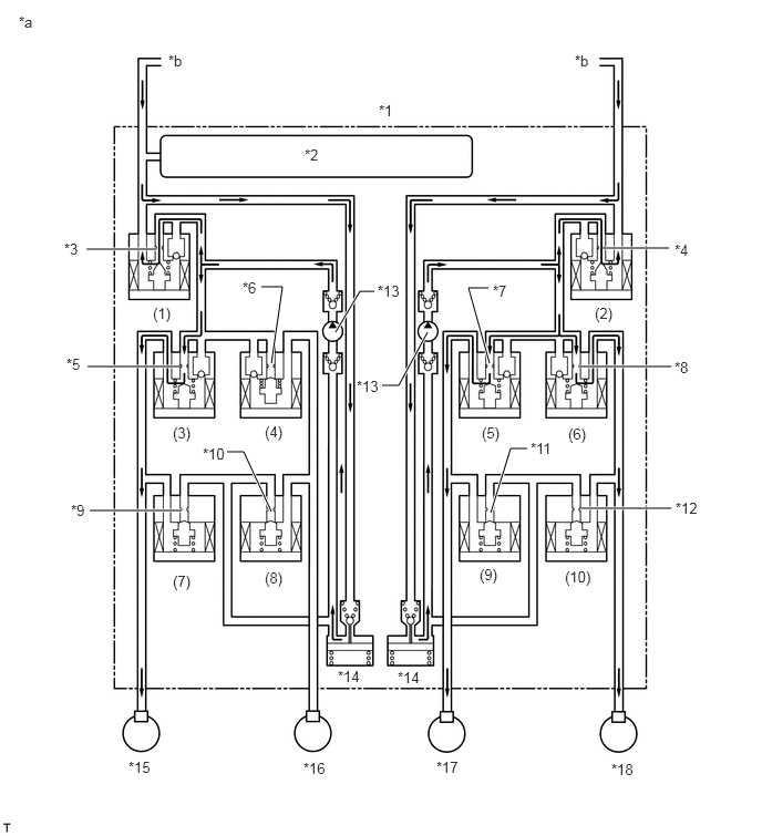
X100725C02
0.813,2.344 1.469,2.344 true 0.823,3.448 1.688,3.448 true 0.844,4.802 1.708,4.802 true 5.667,2.333 6.292,2.333 true 5.438,3.448 6.313,3.448 true 5.469,4.781 6.313,4.781 true 4.615,4.823 4.802,4.219 4.802,4.219 4.958,4.219 true 2.135,4.25 2.292,4.25 2.292,4.25 2.552,4.813 true 2.458,2.698 2.656,2.698 2.656,2.698 2.552,3.417 true 4.604,3.417 4.406,2.708 4.406,2.708 4.594,2.708 true 3.156,3.125 3.385,2.74 3.385,2.74 3.521,2.74 true 4.021,3.125 3.75,3.625 3.75,3.625 3.594,3.625 true 0.177,0.125 0.49,0.323 0.313,0.198 10 *a 3.563,0.958 3.875,1.156 0.313,0.198 10 *1 1.583,0.49 1.896,0.688 0.313,0.198 10 *b 5.406,0.49 5.719,0.688 0.313,0.198 10 *b 2.865,1.375 3.177,1.573 0.313,0.198 10 *2 0.604,2.26 0.917,2.458 0.313,0.198 10 *3 0.625,3.344 0.938,3.542 0.313,0.198 10 *5 1.438,2.865 1.74,3.083 0.302,0.219 10 (1) 2.281,2.625 2.51,2.844 0.229,0.219 10 *6 1.625,3.99 1.906,4.208 0.281,0.219 10 (3) 2.49,3.979 2.729,4.219 0.24,0.24 10 (4) 3.354,3.552 3.74,3.75 0.385,0.198 10 *13 4.635,2.656 4.927,2.875 0.292,0.219 10 *7 6.344,2.271 6.656,2.469 0.313,0.198 10 *4 5.594,2.865 5.844,3.083 0.25,0.219 10 (2) 6.344,3.375 6.531,3.604 0.188,0.229 10 *8 5.344,4 5.563,4.198 0.219,0.198 10 (6) 4.531,3.99 4.813,4.229 0.281,0.24 10 (5) 0.667,4.719 0.979,4.917 0.313,0.198 10 *9 1.625,5.385 1.865,5.635 0.24,0.25 10 (7) 2.49,5.354 2.729,5.583 0.24,0.229 10 (8) 4.51,5.323 4.74,5.573 0.229,0.25 10 (9) 5.313,5.344 5.635,5.573 0.323,0.229 10 (10) 6.354,4.698 6.646,4.938 0.292,0.24 10 *12 1.906,4.188 2.219,4.406 0.313,0.219 10 *10 4.99,4.135 5.24,4.333 0.25,0.198 10 *11 1.208,7.135 1.469,7.375 0.26,0.24 10 *15 2.854,7.146 3.115,7.365 0.26,0.219 10 *16 4.104,7.135 4.354,7.333 0.25,0.198 10 *17 5.75,7.156 6.042,7.385 0.292,0.229 10 *18 3.177,6.281 3.49,6.542 0.313,0.26 10 *14 3.552,2.656 3.938,2.854 0.385,0.198 10 *13 3.74,6.292 4.052,6.552 0.313,0.26 10 *14
*1 Brake Actuator Assembly *2 Master Cylinder Pressure Sensor
*3 Port (A) *4 Port (B)
*5 Port (C) *6 Port (D)
*7 Port (E) *8 Port (F)
*9 Port (G) *10 Port (H)
*11 Port (I) *12 Port (J)
*13 Pump *14 Reservoir
*15 Front Wheel Cylinder RH *16 Rear Wheel Cylinder LH
*17 Rear Wheel Cylinder RH *18 Front Wheel Cylinder LH
*a VSC Operation (Front Wheel Skid Restraining Control) *b From Master Cylinder


Item Port Not Activated Activated
Increase Mode Holding Mode Reduction Mode

*: Hydraulic pressure is controlled by continuously cycling the solenoid valves between open and closed, according to the operating conditions.

Master Cylinder Cut Solenoid Valve (1) (A) OFF (Open) ON* ON* ON*
(2) (B) OFF (Open) ON* ON* ON*
Front Brake Pressure Holding Solenoid Valve (3) (C) OFF (Open) OFF (Open) ON (Closed) ON (Closed)
(6) (F) OFF (Open) OFF (Open) ON (Closed) ON (Closed)
Pressure Reduction Solenoid Valve (7) (G) OFF (Closed) OFF (Closed) OFF (Closed) ON (Open)
(10) (J) OFF (Closed) OFF (Closed) OFF (Closed) ON (Open)
Brake Wheel Cylinder Pressure Right - - Increase Hold Reduce
Left - - Increase Hold Reduce
Rear Brake Pressure Holding Solenoid Valve (4) (D) OFF (Open) ON (Closed) ON (Closed) ON (Closed)
(5) (E) OFF (Open) OFF (Open) ON (Closed) ON (Closed)
Pressure Reduction Solenoid Valve (8) (H) OFF (Closed) OFF (Closed) OFF (Closed) OFF (Closed)
(9) (I) OFF (Closed) OFF (Closed) OFF (Closed) ON (Open)
Brake Wheel Cylinder Pressure Right - - Increase Hold Reduce
Left - - - - -
Pump OFF ON ON ON


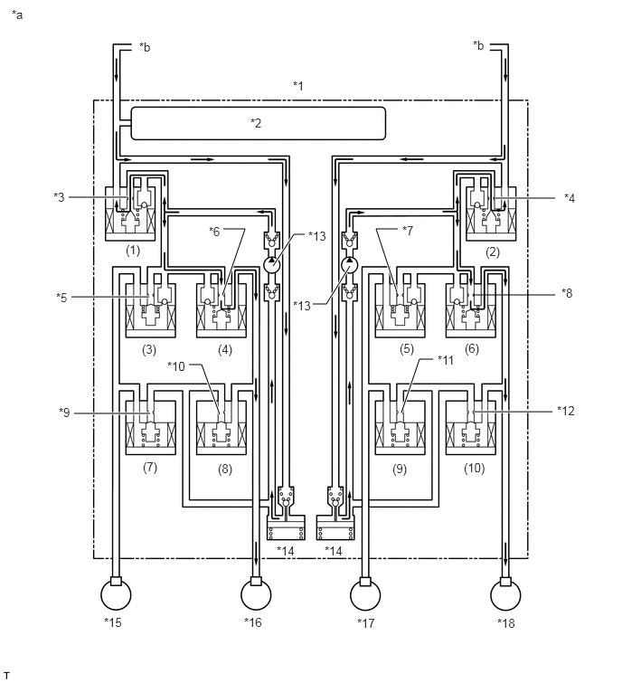
iii.

In rear wheel skid restraining control, the brakes of the front wheels on the outer circle of the turn are applied. Also, depending on whether the brake is on or off and the condition of the vehicle, there are circumstances in which the brake might not be applied to the wheels even if the wheel is targeted for braking. The diagram below shows the hydraulic circuit in the pressure increase mode, as it controls a rear wheel skid condition while the vehicle is making a right turn. In other operating modes, each pressure holding valve and pressure reduction valve is turned on/off according to the ABS with EBD operation patterns.
X100726C02
5.698,2.281 6.396,2.281 true 5.458,3.396 6.396,3.396 false 5.469,4.74 6.365,4.74 true 4.625,4.75 4.833,4.135 4.833,4.135 4.99,4.135 true 2.177,4.198 2.323,4.198 2.323,4.198 2.531,4.771 true 0.854,4.76 1.729,4.76 true 0.823,3.417 1.719,3.417 true 0.792,2.271 1.469,2.271 true 3.146,3.063 3.385,2.698 3.385,2.698 3.51,2.698 true 4.031,3.063 3.76,3.5 3.76,3.5 3.604,3.5 true 2.563,3.396 2.823,2.635 2.823,2.635 2.573,2.635 true 4.573,3.365 4.333,2.635 4.333,2.635 4.583,2.635 true 0.135,0.083 0.448,0.281 0.313,0.198 10 *a 1.604,0.458 1.917,0.656 0.313,0.198 10 *b 5.448,0.438 5.76,0.635 0.313,0.198 10 *b 3.375,0.906 3.688,1.104 0.313,0.198 10 *1 2.885,1.333 3.198,1.531 0.313,0.198 10 *2 0.615,2.188 0.927,2.385 0.313,0.198 10 *3 0.646,3.344 0.958,3.542 0.313,0.198 10 *5 0.677,4.667 0.99,4.865 0.313,0.198 10 *9 1.448,2.792 1.75,3.021 0.302,0.229 10 (1) 2.406,2.583 2.615,2.823 0.208,0.24 10 *6 1.635,3.938 1.885,4.208 0.25,0.271 10 (3) 2.51,3.938 2.771,4.198 0.26,0.26 10 (4) 1.646,5.292 1.885,5.521 0.24,0.229 10 (7) 2.51,5.313 2.844,5.531 0.333,0.219 10 (8) 1.927,4.135 2.292,4.333 0.365,0.198 10 *10 3.552,2.635 3.823,2.927 0.271,0.292 10 *13 4.635,2.573 4.948,2.771 0.313,0.198 10 *7 5.594,2.813 5.854,3.073 0.26,0.26 10 (2) 6.5,2.198 6.813,2.396 0.313,0.198 10 *4 6.469,3.292 6.781,3.49 0.313,0.198 10 *8 6.417,4.646 6.771,4.896 0.354,0.25 10 *12 4.521,5.313 4.823,5.542 0.302,0.229 10 (9) 5.344,5.302 5.729,5.563 0.385,0.26 10 (10) 4.604,3.927 4.958,4.135 0.354,0.208 10 (5) 5.354,3.927 5.656,4.135 0.302,0.208 10 (6) 5.042,4.063 5.333,4.292 0.292,0.229 10 *11 3.188,6.26 3.49,6.448 0.302,0.188 10 *14 1.198,7.083 1.531,7.281 0.333,0.198 10 *15 2.813,7.083 3.156,7.323 0.344,0.24 10 *16 4.115,7.094 4.427,7.302 0.313,0.208 10 *17 5.729,7.094 6.052,7.302 0.323,0.208 10 *18 3.74,6.26 4.042,6.448 0.302,0.188 10 *14 3.375,3.438 3.646,3.729 0.271,0.292 10 *13
*1 Brake Actuator Assembly *2 Master Cylinder Pressure Sensor
*3 Port (A) *4 Port (B)
*5 Port (C) *6 Port (D)
*7 Port (E) *8 Port (F)
*9 Port (G) *10 Port (H)
*11 Port (I) *12 Port (J)
*13 Pump *14 Reservoir
*15 Front Wheel Cylinder RH *16 Rear Wheel Cylinder LH
*17 Rear Wheel Cylinder RH *18 Front Wheel Cylinder LH
*a VSC Operation (Rear Wheel Skid Restraining Control) *b From Master Cylinder


Item Port Not Activated Activated
Increase Mode Holding Mode Reduction Mode

*: Hydraulic pressure is controlled by continuously cycling the solenoid valves between open and closed, according to the operating conditions.

Master Cylinder Cut Solenoid Valve (1) (A) OFF (Open) ON* ON* ON*
(2) (B) OFF (Open) ON* ON* ON*
Front Brake Pressure Holding Solenoid Valve (3) (C) OFF (Open) ON (Closed) ON (Closed) ON (Closed)
(6) (F) OFF (Open) OFF (Open) ON (Closed) ON (Closed)
Pressure Reduction Solenoid Valve (7) (G) OFF (Closed) OFF (Closed) OFF (Closed) OFF (Closed)
(10) (J) OFF (Closed) OFF (Closed) OFF (Closed) ON (Open)
Brake Wheel Cylinder Pressure Right - - - - -
Left - - Increase Hold Reduce
Rear Brake Pressure Holding Solenoid Valve (4) (D) OFF (Open) OFF (Open) ON (Closed) ON (Closed)
(5) (E) OFF (Open) ON (Closed) ON (Closed) ON (Closed)
Pressure Reduction Solenoid Valve (8) (H) OFF (Closed) OFF (Closed) OFF (Closed) ON (Open)
(9) (I) OFF (Closed) OFF (Closed) OFF (Closed) OFF (Closed)
Brake Wheel Cylinder Pressure Right - - - - -
Left - - Increase Hold Reduce
Pump OFF ON ON ON