HEATING / AIR CONDITIONING AIR CONDITIONING SYSTEM DETAILS EVAPORATOR
CONSTRUCTION
Revolutionary Super-Slim Structure (RS) Type Evaporator (Models with 1NZ-FE Engine or 2NZ-FE Engine)
The Revolutionary super-slim Structure (RS) type evaporator is used.
By placing the tanks at the top and the bottom of the No. 1 cooler evaporator sub-assembly and by using a micropore tube construction, the following effects have been achieved:
Heat exchanging efficiency is ensured.
Temperature distribution is made uniform.
The No. 1 cooler evaporator sub-assembly is made thinner.
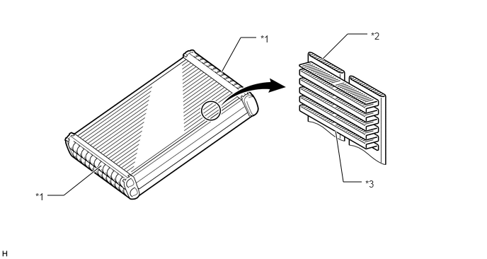
| *1 | Tank | *2 | Micropore Tube |
| *3 | Cooling Fin | - | - |
Beneficial Refrigerant Stream (BRS) Type Evaporator (Models with 1NR-FE Engine or 2NR-FE Engine)
The Beneficial Refrigerant Stream (BRS) type evaporator is used.
The Beneficial Refrigerant Stream (BRS) type evaporator is composed of tanks, tubes and cooling fins. The tubes project outwards and are shaped as a fine duct in an attempt to offer superior conductivity with a narrower width. Furthermore, the evaporator has been drastically miniaturized and lightened through efforts to promote conductivity through shrinking the fin height, tube thickness and fin pitch, as well as by thinning the core material.
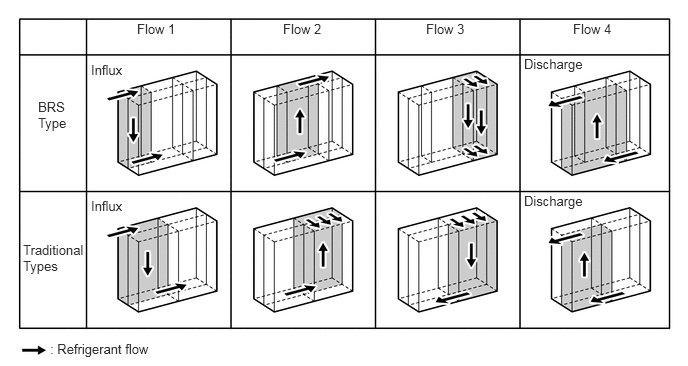
The route that refrigerant passes through within the evaporator is optimized and pressure losses are reduced in an effort to increase performance and decrease size.
While flowing through the evaporator tubes, refrigerant exchanges heat and vaporizes from a mist state.
As shown in the illustration below, the proportion of tubes through which refrigerant flows increases as the direction the refrigerant flows in changes. This makes it easier for refrigerant to flow and decreases pressure losses.