2NR-FE ENGINE MECHANICAL ENGINE UNIT DETAILS VALVE MECHANISM
CONSTRUCTION
Intake and exhaust efficiency has been increased due to the larger total port areas.
The valve mechanism uses a No. 1 valve rocker arm sub-assembly with built-in needle bearings. This reduces the friction that occurs between the cams and the areas on the No. 1 valve rocker arm sub-assemblies that push the valves down, thus improving fuel economy.
Hydraulic valve lash adjuster assemblies, which maintain a constant zero valve clearance through the use of oil pressure and spring force, are used.
A valve spring (outer compression spring), whose upper portion is shaped like a beehive, is used to reduce inertial mass. As a result, the load on the valve spring (outer compression spring) and friction are reduced.
The intake camshaft (camshaft) and exhaust camshaft (No. 2 camshaft) are driven by a timing chain (chain sub-assembly).
This engine uses the dual Variable Valve Timing-intelligent (VVT-i) system which controls the intake and exhaust camshafts to provide optimal valve timing according to driving conditions. With this, lower fuel consumption, higher engine performance, and reduced exhaust emissions have been achieved.
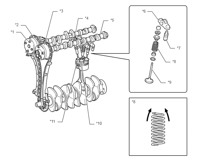
| *1 | Intake VVT-i Controller (Camshaft Timing Gear Assembly) | *2 | Timing Chain (Chain Sub-assembly) |
| *3 | Exhaust VVT-i Controller (Camshaft Timing Exhaust Gear Assembly) | *4 | Intake Camshaft (Camshaft) |
| *5 | Exhaust Camshaft (No. 2 Camshaft) | *6 | No. 1 Valve Rocker Arm Sub-assembly |
| *7 | Valve Lash Adjuster Assembly | *8 | Valve Spring (Outer Compression Spring) |
| *9 | Valve | *10 | Exhaust Valve |
| *11 | Intake Valve | - | - |

|
Beehive | - | - |