NM30M0E
_52
Drivetrain
_018306
C54 MANUAL TRANSMISSION / TRANSAXLE
_0090422
MANUAL TRANSAXLE SYSTEM
DE
DETAILS
F
C54 MANUAL TRANSMISSION / TRANSAXLE MANUAL TRANSAXLE SYSTEM DETAILS SHIFT CONTROL
CONSTRUCTION
a.
Shift and Select Mechanism
i.
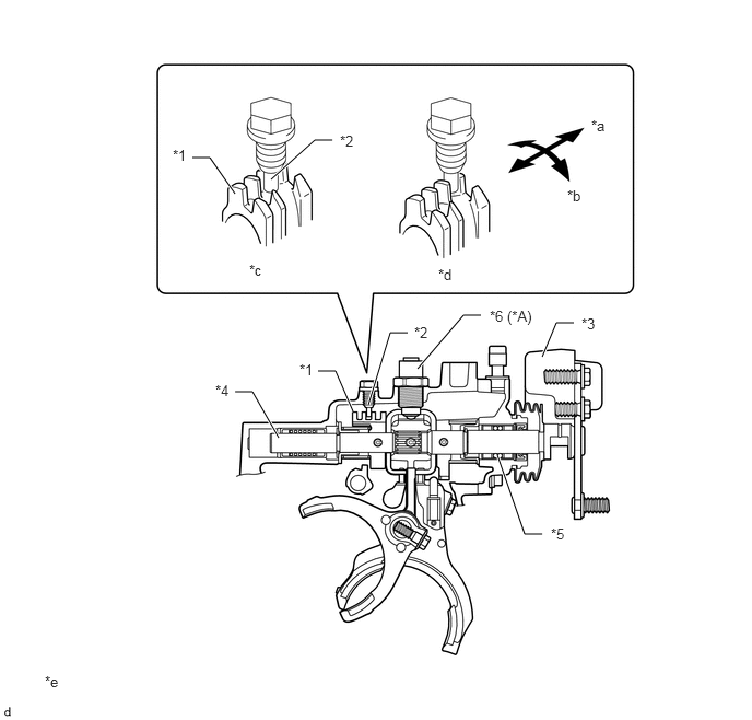
An excellent shift feel has been achieved through the use of the bearing, the No. 2 lock ball assembly* and the shift lever damper on the shift and select lever shaft assembly.
*: Only for TMT made models
ii.
A shift guide plate (No. 2 shift lever inner) is provided on the shift and select lever shaft assembly. The movement distance of the shift and select lever shaft assembly in the select direction after completing the shifting is regulated by the shift guide plate (No. 2 shift lever inner) and shift guide pin (shift gate pin). This clarifies the position of the shift knob and enables accurate shift operations.
2.24,1.844 2,1.5
2,1.5 1.833,1.5
true
3.167,1.333 3,1.333
3,1.333 2.583,1.708
true
5.167,5.083 5,5.083
5,5.083 4.74,4.333
true
5.469,3.073 5.302,3.073
5.302,3.073 5.167,3.396
true
3.885,3.167 3.719,3.167
3.719,3.167 3.51,3.854
true
3.365,3.917 3.198,3.531
3.198,3.531 3.031,3.531
true
2.656,4.167 2.406,3.729
2.406,3.729 2.24,3.729
true
4.583,3 4.417,3
4.417,3 3.979,3.51
true
1.646,1.396 1.958,1.552
0.313,0.156
10
false
*1
3.24,1.26 3.552,1.417
0.313,0.156
10
false
*2
5.542,3 5.854,3.156
0.313,0.156
10
false
*3
2.052,3.635 2.365,3.792
0.313,0.156
10
false
*4
5.25,5 5.563,5.156
0.313,0.156
10
false
*5
5.635,1.115 5.948,1.271
0.313,0.156
10
false
*a
5.406,1.781 5.719,1.938
0.313,0.156
10
false
*b
2.375,2.49 2.688,2.646
0.313,0.156
10
false
*c
4.177,2.531 4.49,2.688
0.313,0.156
10
false
*d
3.948,3.083 4.26,3.24
0.313,0.156
10
false
*2
2.854,3.438 3.167,3.594
0.313,0.156
10
false
*1
0.427,6.406 0.74,6.563
0.313,0.156
10
false
*e
4.667,2.927 5.313,3.083
0.646,0.156
10
false
*6 (*A)
| *A | TMT Made Models | - | - |
| *1 | Shift Guide Plate (No. 2 Shift Lever Inner) | *2 | Shift Guide Pin (Shift Gate Pin) |
| *3 | Shift Lever Damper | *4 | Shift and Select Lever Shaft Assembly |
| *5 | Bearing | *6 | No. 2 Lock Ball Assembly |
| *a | Select Direction | *b | Shift Direction |
| *c | Neutral Position | *d | Shift Completed |
| *e | The illustrations shown are examples only. | - | - |