NETWORKING LIN COMMUNICATION SYSTEM TERMINALS OF ECU
CHECK CERTIFICATION ECU (SMART KEY ECU ASSEMBLY) (w/ Smart Entry and Start System)
Disconnect the certification ECU (smart key ECU assembly) connector.
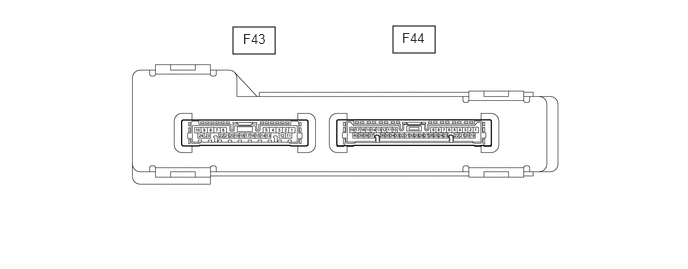
Measure the voltage and resistance according to the value(s) in the table below.
- HINT:
-
Measure the values on the wire harness side with the connector disconnected.
| Tester Connection | Wiring Color | Terminal Description | Condition | Specified Condition |
|---|---|---|---|---|
| F43-10 (E) - Body ground | W-B - Body ground | Ground | Always | Below 1 Ω |
| F43-1 (+B) - Body ground | B - Body ground | +B power supply | Always | 11 to 14 V |
If the result is not as specified, there may be a malfunction in the wire harness.
Reconnect the certification ECU (smart key ECU assembly) connector.
Check for pulses according to the value(s) in the table below.
| Tester Connection | Wiring Color | Terminal Description | Switch Condition | Specified Condition |
|---|---|---|---|---|
| F43-5 (LIN) - Body ground | LG - Body ground | LIN communication line | Ignition switch ON | Pulse generation |
If the result is not as specified, the certification ECU (smart key ECU assembly) may be malfunctioning.
CHECK STEERING LOCK ECU (STEERING LOCK ACTUATOR ASSEMBLY) (w/ Smart Entry and Start System)
Disconnect the steering lock ECU (steering lock actuator assembly) connector.

Measure the resistance and voltage according to the value(s) in the table below.
| Terminal No. (Symbol) | Wiring Color | Terminal Description | Condition | Specified Condition |
|---|---|---|---|---|
| F15-1 (GND) - Body ground | W-B Body ground | Ground | Always | Below 1 Ω |
| F15-7 (B) - Body ground | P - Body ground | Battery power supply | Always | 11 to 14 V |
If the result is not as specified, there may be a malfunction on the wire harness side.
Reconnect the F15 steering lock ECU (steering lock actuator assembly) connector.
Check for pulses according to the value(s) in the table below.
| Tester Connection | Wiring Color | Terminal Description | Switch Condition | Specified Condition |
|---|---|---|---|---|
| F15-5 (LIN) - Body ground | R - Body ground | LIN communication line | Ignition switch ON | Pulse generation |
If the result is not as specified, the steering lock ECU (steering lock actuator assembly) may be malfunctioning.