WINDOW / GLASS POWER WINDOW CONTROL SYSTEM TERMINALS OF ECU
CHECK POWER WINDOW REGULATOR MASTER SWITCH ASSEMBLY
for LHD
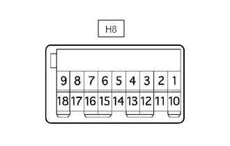
Disconnect the power window regulator master switch assembly connector.
Measure the voltage and resistance according to the value(s) in the table below.
- HINT:
-
Measure the values on the wire harness side with the connector disconnected.
| Terminal No. (Symbol) | Wiring Color | Terminal Description | Condition | Specified Condition |
|---|---|---|---|---|
| H8-6 (B) - H8-1 (E) | V - W-B | Power supply | Ignition switch ON | 11 to 14 V |
| H8-1 (E) - Body ground | W-B - Body ground | Ground | Always | Below 1 Ω |
If the result is not as specified, there may be a malfunction in the wire harness.
Reconnect the power window regulator master switch assembly connector.
Measure the voltage according to the value(s) in the table below.
| Terminal No. (Symbol) | Wiring Color | Terminal Description | Condition | Specified Condition |
|---|---|---|---|---|
| H8-8 (U) - H8-1 (E) | R - W-B | Power window motor UP operation | Ignition switch ON, driver side door power window switch OFF → UP (Manual operation) | 11 to 14 V → Below 1 V |
| H8-5 (D) - H8-1 (E) | SB - W-B | Power window motor DOWN operation | Ignition switch ON, driver side door power window switch OFF → DOWN (Manual operation) | 11 to 14 V → Below 1 V |
| H8-4 (AUTO) - H8-1 (E) | BR - W-B | Power window motor AUTO operation | Ignition switch ON, driver side door glass fully opened → driver side power window AUTO UP operation → driver side door glass fully closed | 11 to 14 V → Below 1 V → 11 to 14 V |
| Ignition switch ON, driver side door glass fully closed → driver side power window AUTO DOWN operation → driver side door glass fully opened | 11 to 14 V → Below 1 V → 11 to 14 V | |||
| H8-3 (LED+) - H8-1 (E) | P - W-B | LED illumination signal | Ignition switch ON | 11 to 14 V |
| Ignition switch turned off | Below 1 V |
If the result is not as specified, the power window regulator master switch assembly may have a malfunction.
for RHD
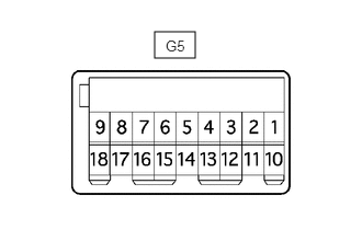
Disconnect the power window regulator master switch assembly connector.
Measure the voltage and resistance according to the value(s) in the table below.
- HINT:
-
Measure the values on the wire harness side with the connector disconnected.
| Terminal No. (Symbol) | Wiring Color | Terminal Description | Condition | Specified Condition |
|---|---|---|---|---|
| G5-6 (B) - G5-9 (E) | V - W-B | Power supply | Ignition switch ON | 11 to 14 V |
| G5-9 (E) - Body ground | W-B - Body ground | Ground | Always | Below 1 Ω |
If the result is not as specified, there may be a malfunction in the wire harness.
Reconnect the power window regulator master switch assembly connector.
Measure the voltage according to the value(s) in the table below.
| Terminal No. (Symbol) | Wiring Color | Terminal Description | Condition | Specified Condition |
|---|---|---|---|---|
| G5-1 (U) - G5-9 (E) | R - W-B | Power window motor UP operation | Ignition switch ON, driver side door power window switch OFF → UP (Manual operation) | 11 to 14 V → Below 1 V |
| G5-5 (D) - G5-9 (E) | SB - W-B | Power window motor DOWN operation | Ignition switch ON, driver side door power window switch OFF → DOWN (Manual operation) | 11 to 14 V → Below 1 V |
| G5-4 (AUTO) - G5-9 (E) | BR - W-B | Power window motor AUTO operation | Ignition switch ON, driver side door glass fully opened → driver side power window AUTO UP operation → driver side door glass fully closed | 11 to 14 V → Below 1 V → 11 to 14 V |
| Ignition switch ON, driver side door glass fully closed → driver side power window AUTO DOWN operation → driver side door glass fully opened | 11 to 14 V → Below 1 V → 11 to 14 V | |||
| G5-3 (LED+) - G5-9 (E) | P - W-B | LED illumination signal | Ignition switch ON | 11 to 14 V |
| Ignition switch turned off | Below 1 V |
If the result is not as specified, the power window regulator master switch assembly may have a malfunction.
CHECK POWER WINDOW REGULATOR SWITCH ASSEMBLY LH OR RH
for LHD
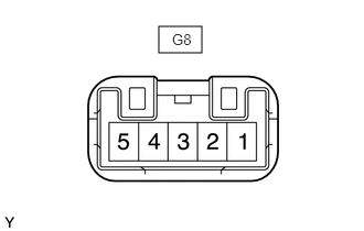
Disconnect the power window regulator switch assembly RH connector.
Measure the voltage according to the value(s) in the table below.
| Terminal No. (Symbol) | Wiring Color | Terminal Description | Condition | Specified Condition |
|---|---|---|---|---|
| G8-3 (B) - Body ground | B - Body ground | Power supply | Ignition switch ON | 11 to 14 V |
| G8-5 (SU) - Body ground | P - Body ground | Ground | Always | Below 1 Ω |
| G8-2 (SD) - Body ground | R - Body ground | Ground | Always | Below 1 Ω |
If the result is not as specified, there may be a malfunction in the wire harness.
Reconnect the power window regulator switch assembly RH connector.
Measure the voltage according to the value(s) in the table below.
| Terminal No. (Symbol) | Wiring Color | Terminal Description | Condition | Specified Condition |
|---|---|---|---|---|
| G8-4 (U) - Body ground | LA-R - Body ground | Power window motor UP operation | Power window regulator switch assembly RH OFF → UP | Below 1 V → 11 to 14 V |
| G8-1 (D) - Body ground | LA-SB - Body ground | Power window motor DOWN operation | Power window regulator switch assembly RH OFF → DOWN | Below 1 V → 11 to 14 V |
If the result is not as specified, the power window regulator switch assembly RH may have a malfunction.
for RHD
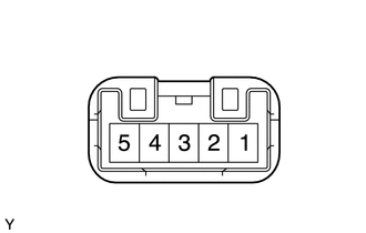
Disconnect the power window regulator switch assembly LH connector.
Measure the voltage according to the value(s) in the table below.
| Terminal No. (Symbol) | Wiring Color | Terminal Description | Condition | Specified Condition |
|---|---|---|---|---|
| H1-3 (B) - Body ground | L - Body ground | Power supply | Ignition switch ON | 11 to 14 V |
| H1-5 (SU) - Body ground | LG - Body ground | Ground | Always | Below 1 Ω |
| H1-2 (SD) - Body ground | P - Body ground | Ground | Always | Below 1 Ω |
If the result is not as specified, there may be a malfunction in the wire harness.
Reconnect the power window regulator switch assembly LH connector.
Measure the voltage according to the value(s) in the table below.
| Terminal No. (Symbol) | Wiring Color | Terminal Description | Condition | Specified Condition |
|---|---|---|---|---|
| H1-4 (U) - Body ground | LA-R - Body ground | Power window motor UP operation | Power window regulator switch assembly LH OFF → UP | Below 1 V → 11 to 14 V |
| H1-1 (D) - Body ground | LA-SB - Body ground | Power window motor DOWN operation | Power window regulator switch assembly LH OFF → DOWN | Below 1 V → 11 to 14 V |
If the result is not as specified, the power window regulator switch assembly LH may have a malfunction.
CHECK REAR POWER WINDOW REGULATOR SWITCH ASSEMBLY LH
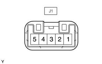
Disconnect the rear power window regulator switch assembly LH connector.
Measure the voltage according to the value(s) in the table below.
| Terminal No. (Symbol) | Wiring Color | Terminal Description | Condition | Specified Condition |
|---|---|---|---|---|
| J1-3 (B) - Body ground | LA-P - Body ground | Power supply | Ignition switch ON | 11 to 14 V |
| J1-5 (SU) - Body ground | LA-BE - Body ground | Ground | Always | Below 1 Ω |
| J1-2 (SD) - Body ground | LA-G - Body ground | Ground | Always | Below 1 Ω |
Reconnect the rear power window regulator switch assembly LH connector.
Measure the voltage according to the value(s) in the table below.
| Terminal No. (Symbol) | Wiring Color | Terminal Description | Condition | Specified Condition |
|---|---|---|---|---|
| J1-4 (U) - Body ground | R - Body ground | Power window motor UP operation | Rear power window regulator switch assembly LH OFF → UP | Below 1 V → 11 to 14 V |
| J1-1 (D) - Body ground | SB - Body ground | Power window motor DOWN operation | Rear power window regulator switch assembly LH OFF → DOWN | Below 1 V → 11 to 14 V |
If the result is not as specified, the rear power window regulator switch assembly LH may have a malfunction.
CHECK REAR POWER WINDOW REGULATOR SWITCH ASSEMBLY RH
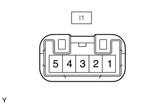
Disconnect the rear power window regulator switch assembly RH connector.
Measure the voltage according to the value(s) in the table below.
| Terminal No. (Symbol) | Wiring Color | Terminal Description | Condition | Specified Condition |
|---|---|---|---|---|
| I1-3 (B) - Body ground | LA-P - Body ground | Power supply | Ignition switch ON | 11 to 14 V |
| I1-5 (SU) - Body ground | LA-GR - Body ground | Ground | Always | Below 1 Ω |
| I1-2 (SD) - Body ground | LA-L - Body ground | Ground | Always | Below 1 Ω |
Reconnect the rear power window regulator switch assembly RH connector.
Measure the voltage according to the value(s) in the table below.
| Terminal No. (Symbol) | Wiring Color | Terminal Description | Condition | Specified Condition |
|---|---|---|---|---|
| I1-4 (U) - Body ground | R - Body ground | Power window motor UP operation | Rear power window regulator switch assembly RH OFF → UP | Below 1 V → 11 to 14 V |
| I1-1 (D) - Body ground | SB - Body ground | Power window motor DOWN operation | Rear power window regulator switch assembly RH OFF → DOWN | Below 1 V → 11 to 14 V |
If the result is not as specified, the rear power window regulator switch assembly RH may have a malfunction.
CHECK FRONT POWER WINDOW REGULATOR MOTOR ASSEMBLY LH OR RH
for LHD
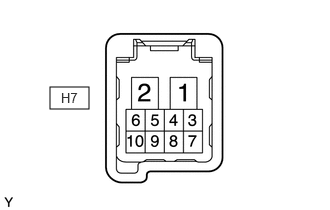
Disconnect the front power window regulator motor assembly LH connector.
Measure the voltage and resistance according to the value(s) in the table below.
- HINT:
-
Measure the values on the wire harness side with the connector disconnected.
| Terminal No. (Symbol) | Wiring Color | Terminal Description | Condition | Specified Condition |
|---|---|---|---|---|
| H7-1 (GND) - Body ground | W-B - Body ground | Ground | Always | Below 1 Ω |
| H7-2 (B) - H7-1 (GND) | GR - W-B | Power supply | Always | 11 to 14 V |
| H7-6 (IG) - H7-1 (GND) | G - W-B | IG signal | Ignition switch ON | 11 to 14 V |
If the result is not as specified, there may be a malfunction in the wire harness.
Reconnect the front power window regulator motor assembly LH connector.
Measure the voltage according to the value(s) in the table below.
| Terminal No. (Symbol) | Wiring Color | Terminal Description | Condition | Specified Condition |
|---|---|---|---|---|
| H7-10 (UP) - H7-1 (GND) | R - W-B | Power window motor UP operation | Ignition switch ON, driver side door power window switch OFF → UP (Manual operation) | 11 to 14 V → Below 1 V |
| H7-7 (DOWN) - H7-1 (GND) | SB - W-B | Power window motor DOWN operation | Ignition switch ON, driver side door power window switch OFF → DOWN (Manual operation) | 11 to 14 V → Below 1 V |
| H7-4 (AUTO) - H7-1 (GND) | BR - W-B | Power window motor AUTO operation | Ignition switch ON, driver side door glass fully opened → driver side power window AUTO UP operation → driver side door glass fully closed | 11 to 14 V → Below 1 V → 11 to 14 V |
| Ignition switch ON, driver side door glass fully closed → driver side power window AUTO DOWN operation → driver side door glass fully opened | 11 to 14 V → Below 1 V → 11 to 14 V | |||
| H7-5 (LED) - H7-1 (GND) | P - W-B | LED illumination signal | Ignition switch ON | 11 to 14 V |
| Ignition switch off | Below 1 V |
If the result is not as specified, the front power window regulator motor assembly LH may have a malfunction.
for RHD
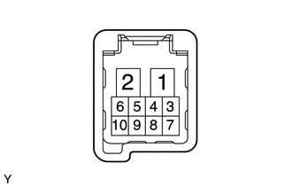
Disconnect the front power window regulator motor assembly RH connector.
Measure the voltage and resistance according to the value(s) in the table below.
- HINT:
-
Measure the values on the wire harness side with the connector disconnected.
| Terminal No. (Symbol) | Wiring Color | Terminal Description | Condition | Specified Condition |
|---|---|---|---|---|
| G1-1 (GND) - Body ground | W-B - Body ground | Ground | Always | Below 1 Ω |
| G1-2 (B) - G1-1 (GND) | GR - W-B | Power supply | Always | 11 to 14 V |
| G1-6 (IG) - G1-1 (GND) | G - W-B | IG signal | Ignition switch ON | 11 to 14 V |
If the result is not as specified, there may be a malfunction in the wire harness.
Reconnect the front power window regulator motor assembly RH connector.
Measure the voltage according to the value(s) in the table below.
| Terminal No. (Symbol) | Wiring Color | Terminal Description | Condition | Specified Condition |
|---|---|---|---|---|
| G1-10 (UP) - G1-1 (GND) | R - W-B | Power window motor UP operation | Ignition switch ON, driver side door power window switch OFF → UP (Manual operation) | 11 to 14 V → Below 1 V |
| G1-7 (DOWN) - G1-1 (GND) | SB - W-B | Power window motor DOWN operation | Ignition switch ON, driver side door power window switch OFF → DOWN (Manual operation) | 11 to 14 V → Below 1 V |
| G1-4 (AUTO) - G1-1 (GND) | BR - W-B | Power window motor AUTO operation | Ignition switch ON, driver side door glass fully opened → driver side power window AUTO UP operation → driver side door glass fully closed | 11 to 14 V → Below 1 V → 11 to 14 V |
| Ignition switch ON, driver side door glass fully closed → driver side power window AUTO DOWN operation → driver side door glass fully opened | 11 to 14 V → Below 1 V → 11 to 14 V | |||
| G1-5 (LED) - G1-1 (GND) | P - W-B | LED illumination signal | Ignition switch ON | 11 to 14 V |
| Ignition switch off | Below 1 V |
If the result is not as specified, the front power window regulator motor assembly RH may have a malfunction.