RM30M0E
_58
Vehicle Interior
_017118
HEATING / AIR CONDITIONING
_0086991
AIR CONDITIONING SYSTEM(for Manual Air Conditioning System)
J
HEATING / AIR CONDITIONING AIR CONDITIONING SYSTEM(for Manual Air Conditioning System) IG Power Source Circuit
DESCRIPTION
The main power source supplied to the air conditioning amplifier assembly when the ignition switch is turned to ON. The power source is used for operating components, such as the air conditioning amplifier assembly.
WIRING DIAGRAM
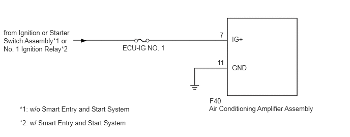
0.073,0.583 1.5,1.188
1.427,0.604
10
false
from Ignition or Starter Switch Assembly*1 or No. 1 Ignition Relay*2
0.406,2.146 2.74,2.375
2.333,0.229
10
false
*1: w/o Smart Entry and Start System
0.406,2.427 2.74,2.656
2.333,0.229
10
false
*2: w/ Smart Entry and Start System
2.51,0.896 4.344,1.094
1.833,0.198
10
false
ECU-IG NO. 1
4.281,2.135 6.563,2.302
2.281,0.167
10
false
Air Conditioning Amplifier Assembly
4.292,1.979 6.125,2.177
1.833,0.198
10
false
F40
4.75,0.719 5,0.917
0.25,0.198
10
false
IG+
4.75,1.302 5.25,1.583
0.5,0.281
10
false
GND
4.5,0.635 4.667,0.833
0.167,0.198
10
false
7
4.448,1.198 4.615,1.396
0.167,0.198
10
false
11
CAUTION / NOTICE / HINT
- NOTICE:
-
Inspect the fuses for circuits related to this system before performing the following procedure.
PROCEDURE
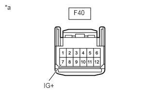
1.CHECK HARNESS AND CONNECTOR (AIR CONDITIONING AMPLIFIER ASSEMBLY - POWER SOURCE)
a.
1.479,0.167 1.948,0.417
0.469,0.25
1.313,1.385 1.052,1.729
true
1.583,0.188 2.042,0.385
0.458,0.198
10
false
F40
0.938,1.75 1.396,1.948
0.458,0.198
10
false
IG+
0.104,0.073 0.563,0.271
0.458,0.198
10
false
*a
| *a | Front view of wire harness connector (to Air Conditioning Amplifier Assembly) |
Disconnect the air conditioning amplifier assembly connector.
b.
Measure the voltage according to the value(s) in the table below.
- Standard Voltage:
Tester Connection Switch Condition Specified Condition F40-7 (IG+) - Body ground Ignition switch off Below 1 V F40-7 (IG+) - Body ground Ignition switch ON 11 to 14 V
- Result:
Proceed to OK NG
OK
2.CHECK HARNESS AND CONNECTOR (AIR CONDITIONING AMPLIFIER ASSEMBLY - BODY GROUND)
NG
REPAIR OR REPLACE HARNESS OR CONNECTOR
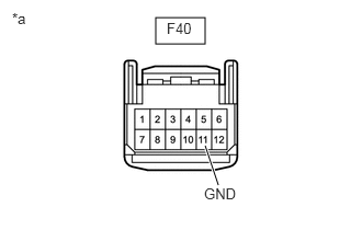
2.CHECK HARNESS AND CONNECTOR (AIR CONDITIONING AMPLIFIER ASSEMBLY - BODY GROUND)
a.
1.479,0.167 1.948,0.417
0.469,0.25
1.948,1.385 2.073,1.76
true
1.583,0.188 2.042,0.385
0.458,0.198
10
false
F40
1.938,1.76 2.396,1.958
0.458,0.198
10
false
GND
0.115,0.094 0.573,0.292
0.458,0.198
10
false
*a
| *a | Front view of wire harness connector (to Air Conditioning Amplifier Assembly) |
Disconnect the air conditioning amplifier assembly connector.
b.
Measure the resistance according to the value(s) in the table below.
- Standard Resistance:
Tester Connection Condition Specified Condition F40-11 (GND) - Body ground Always Below 1 Ω
- Result:
Proceed to OK NG
OK
PROCEED TO NEXT SUSPECTED AREA SHOWN IN PROBLEM SYMPTOMS TABLE
NG
REPAIR OR REPLACE HARNESS OR CONNECTOR