HEATING / AIR CONDITIONING AIR CONDITIONING PRESSURE SENSOR(for 1NZ-FE, 2NZ-FE) ON-VEHICLE INSPECTION
PROCEDURE

 88645H
1.INSPECT NO. 1 PRESSURE SWITCH (for Magnet Clutch Control)
- HINT:
- ·
The pressure switch is installed on the air conditioning pipe on the high pressure side.
- ·
The pressure switch has two functions. It detects abnormal pressure in the air conditioning cycle and turns the compressor on or off as necessary (magnet clutch control). It also turns the condenser fan on or off in accordance with pressure in the cycle (cooling fan control).
- ·
The switch on the low pressure side detects a drop in refrigerant pressure, such as from refrigerant leakage, etc. and turns the magnet clutch off (*1) to prevent damage to the compressor.
- ·
The switch on the high pressure side detects abnormally high pressure in the air conditioning cycle and turns the magnet clutch off (*1) to prevent damage to parts in the air conditioning cycle.
(*1): The ECM turns the magnet clutch on or off upon receiving the signal from the pressure switch.
- ·
As the pressure switch operates when there is a malfunction with the refrigerant pressure, its function cannot be inspected on-vehicle. Follow the procedures below to inspect it.
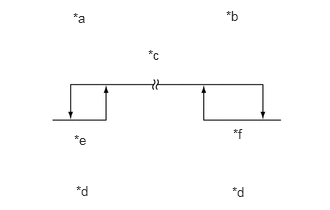
| *a | Low pressure side |
| *b | High pressure side |
| *c | ON (Below 1.0 Ω) |
| *d | OFF (10 KΩ or higher) |
| *e | 196 kPa (2.0 kgf/cm2, 28 psi) |
| *f | 3140 kPa (32.0 kgf/cm2, 455 psi) |
Inspect refrigerant pressure in air conditioning cycle.
Read the manifold gauge pressure when the specified conditions are established.
Temperature at the air inlet with the switch set at RECIRC is 30 to 35°C (86 to 95°F)
Engine running at 1500 rpm
Blower speed control switch at "4" position
Temperature control dial at "MAX COOL" position
Fully open doors
- Standard:
Pressure on high pressure side:
1370 to 1570 kPa (13.9 to 16.0 kgf/cm2, 198 to 228 psi)
- HINT:
- ·
If the refrigerant pressure is not within the standard value, inspect and repair the air conditioning cycle.
- ·
Proceed to step (b) if the refrigerant pressure is within the specified range.
- ·
If the refrigerant pressure is below 196 kPa (2.0 kgf/cm2, 28 psi), the refrigerant amount in the air conditioning cycle may have decreased significantly for reasons such as a gas leakage.
Check air conditioning operation.
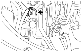
Disconnect the connector.
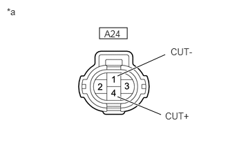
| *a | Front view of wire harness connector
(No. 1 Pressure Switch) |
Connect terminals 1 (CUT-) and 4 (CUT+) of the connector of the No. 1 pressure switch on the vehicle wire harness side using a service wire.
Start the engine.
Turn the air conditioning switch on and check that the magnet clutch is turned on.
Check that the magnet clutch is turned off when disconnecting terminals 1 and 4 (that are connected in the prior step).
- Standard:
Terminals 1 (CUT-) and 4 (CUT+) connected: magnet clutch is on
Terminals 1 (CUT-) and 4 (CUT+) disconnected: magnet clutch is off
Replace the No. 1 pressure switch if the magnet clutch is operated normally. Inspect and repair the wire harness between the No. 1 pressure switch and ECM.
88645H
2.INSPECT NO. 1 PRESSURE SWITCH (for Cooling Fan Control)
- HINT:
-
The switch turns the condenser fan on or off in accordance with pressure in the cycle so that heat exchange in the condenser can be effectively within the normal pressure range.
Install the manifold gauge.
Disconnect the connector.
| *a | Front view of wire harness connector
(No. 1 Pressure Switch) |
Connect terminals 1 (CUT-) and 4 (CUT+) using a tool such as a service wire.
Connect the positive (+) lead from the ohmmeter to terminal 2 and the negative (-) lead to terminal 3.
Start the engine and turn the cooler volume switch on.
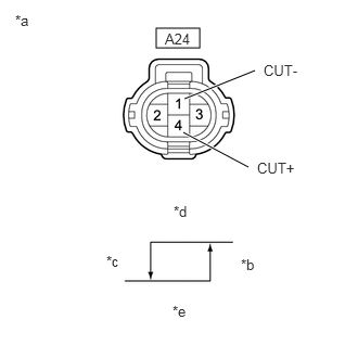
| *a | Front view of wire harness connector
(No. 1 Pressure Switch) |
| *b | ON (Below 1.0 Ω) |
| *c | OFF (10 KΩ or higher) |
| *d | 1226 kPa (12.5 kgf/cm2, 178 psi) |
| *e | 1520 kPa (15.5 kgf/cm2, 220 psi) |
Check that the continuity between terminals 2 and 3 changes in accordance with the refrigerant pressure as shown in the illustration on the left.
- OK:
Changes in accordance with the refrigerant pressure as shown in the illustration.
If the operation is not as specified, replace the No. 1 pressure switch.