FRONT SUSPENSION FRONT LOWER SUSPENSION ARM(for LH Side) INSTALLATION
PROCEDURE

 48069
1.TEMPORARILY TIGHTEN FRONT LOWER NO. 1 SUSPENSION ARM SUB-ASSEMBLY LH
Temporarily tighten the front lower No. 1 suspension arm sub-assembly LH with the 2 bolts.
Install the front lower No. 1 suspension arm sub-assembly LH to the front axle assembly with a new castle nut.
- NOTICE:
-
Do not damage the front disc brake dust cover.
Using a 19 mm ball joint lock nut wrench, fully tighten the castle nut.
- Torque:
- 98 N*m (999 kgf*cm, 72 ft.*lbf)
- NOTICE:
- ·
Use the formula to calculate special torque values for situations where a ball joint lock nut wrench is combined with a torque wrench.
Click hereGeneral>INTRODUCTION>REPAIR INSTRUCTION>PRECAUTION
·If the holes for the clip are not aligned, tighten the castle nut by a further turn of up to 60°.
·Do not allow any oil or grease to contact the threaded or tapered portions of the front lower No. 1 suspension arm sub-assembly LH.
·Do not damage the front disc brake dust cover.
Install a new clip.
2.INSTALL FRONT WHEEL
- Torque:
- 103 N*m (1050 kgf*cm, 76 ft.*lbf)
3. STABILIZE SUSPENSION
Lower the vehicle.
Bounce the vehicle up and down several times to stabilize the suspension.
48819A
4.INSTALL FRONT STABILIZER BOLT
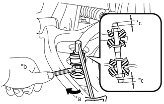
| *a | Turn |
| *b | Hold |
| *c | Protrusion Length |
Install the 4 front stabilizer cushion retainers, front No. 2 stabilizer cushion retainer, 4 front stabilizer cushions and front stabilizer bolt.
While holding the front stabilizer bolt with a wrench, install 2 new nuts.
- Torque:
- 12 N*m (122 kgf*cm, 9 ft.*lbf)
- Standard Protrusion Length:
2.8 to 4.3 mm (0.110 to 0.169 in.)
48069
5.FULLY TIGHTEN FRONT LOWER NO. 1 SUSPENSION ARM SUB-ASSEMBLY LH
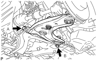
Fully tighten the 2 bolts.
- Torque:
- Bolt A : 112 N*m (1142 kgf*cm, 83 ft.*lbf)
- Bolt B : 165 N*m (1683 kgf*cm, 122 ft.*lbf)
51405A
6.INSTALL NO. 1 ENGINE UNDER COVER SUB-ASSEMBLY (w/ Metal Type Under Cover)
51451A
7.INSTALL CENTER ENGINE UNDER COVER (w/ Metal Type Under Cover)
8.INSPECT AND ADJUST FRONT WHEEL ALIGNMENT