POWER ASSIST SYSTEMS POWER STEERING SYSTEM TERMINALS OF ECU
CHECK POWER STEERING ECU ASSEMBLY
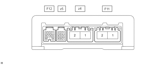
Measure the voltage, resistance and check for pulses according to the value(s) in the table below.
- NOTICE:
- ·
Check if the power steering ECU assembly connectors are securely connected by pulling on them from the backside.
·If the power steering warning light is illuminated due to a malfunction, the fail-safe function may cause the voltage of the power steering ECU assembly terminals to become 0 V.
| Terminal No. (Symbol) | Wiring Color | Terminal Description | Condition | Specified Condition |
|---|---|---|---|---|
| F11-1 (PIG) - F11-2 (PGND) | B - W-B | Power source | Always | 11 to 14 V |
| F11-2 (PGND) - Body ground | W-B - Body ground | Body ground | Always | Below 1 Ω |
| F12-1 (IG) - F11-2 (PGND) | L - W-B | IG power source | Ignition switch ON | 11 to 14 V |
| F12-2 (SPD) - F11-2 (PGND) | P - W-B | Vehicle speed signal | Vehicle being driven | Pulse generation (see waveform 1) |
| F12-3 (TC) - F11-2 (PGND) | L - W-B | TC terminal | Ignition switch ON | 11 to 14 V |
| F12-4 (SIL) - F11-2 (PGND) | B - W-B | GTS communication line | ·
Ignition switch ON ·
Communication not performed with GTS |
11 to 14 V |
| F12-5 (TACH) - F11-2 (PGND) | W - W-B | Engine speed signal | Engine running | Pulse generation (see waveform 2) |
| F12-6 (TS) - F11-2 (PGND) | GR - W-B | TS terminal | Ignition switch ON | 11 to 14 V |
| F12-9 (IDUP) - F11-2 (PGND) | B - W-B | ECM | Ignition switch ON | 5 to 14 V |
| F12-10 (WL) - F11-2 (PGND) | R - W-B | Power steering warning light output signal | ·
Engine running ·
Power steering warning light off |
Below 0.2 V |
·
Ignition switch ON ·
Power steering warning light on |
5.5 to 7 V | |||
| z4-1 (M1) - F11-2 (PGND) | R - W-B | Power steering motor assembly | ·
Ignition switch ON ·
Steering wheel turned to left |
6 to 11 V |
·
Ignition switch ON ·
Steering wheel turned to right |
11 to 14 V | |||
| z4-2 (M2) - F11-2 (PGND) | B - W-B | Power steering motor assembly | ·
Ignition switch ON ·
Steering wheel turned to left |
11 to 14 V |
·
Ignition switch ON ·
Steering wheel turned to right |
6 to 11 V | |||
| z5-1 (TRQ2) - z5-2 (TRQG) | Y - B | Torque sensor | Engine running, steering wheel not turned (without load) | 2.3 to 2.7 V |
| Engine running, steering wheel turned to right with vehicle stopped | 1.2 to 2.5 V | |||
| Engine running, steering wheel turned to left with vehicle stopped | 2.5 to 3.8 V | |||
| z5-2 (TRQG) - F11-2 (PGND) | B - W-B | Torque sensor | Always | Below 1 Ω |
| z5-8 (TRQV) - z5-2 (TRQG) | R - B | Torque sensor | Ignition switch ON | 4.5 to 5.5 V |
| z5-9 (TRQ1) - z5-2 (TRQG) | W - B | Torque sensor | Engine running, steering wheel not turned (without load) | 2.3 to 2.7 V |
| Engine running, steering wheel turned to right with vehicle stopped | 2.5 to 3.8 V | |||
| Engine running, steering wheel turned to left with vehicle stopped | 1.2 to 2.5 V |
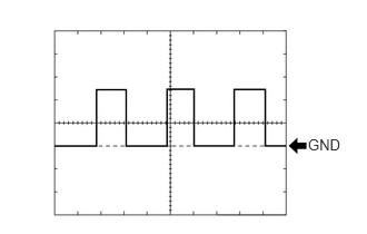
Using an oscilloscope, check waveform 1.
| Item | Contents |
|---|---|
| Terminal No. (Symbol) | F12-2 (SPD) - F11-2 (PGND) |
| Tool Setting | 5 V/DIV., 20 ms./DIV. |
| Vehicle Condition | Vehicle being driven at approximately 20 km/h (12 mph) |
- HINT:
-
The wavelength becomes shorter as the vehicle speed increases.
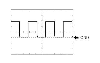
Using an oscilloscope, check waveform 2.
| Item | Contents |
|---|---|
| Terminal No. (Symbol) | F12-5 (TACH) - F11-2 (PGND) |
| Tool Setting | 5 V/DIV., 10 ms./DIV. |
| Vehicle Condition | Idling |
- HINT:
-
The wavelength becomes shorter as the engine speed increases.