Home › Engine / Hybrid System › 1NZ-FE ENGINE CONTROL › SFI SYSTEM(for Automatic Transaxle) › 2013.08–2016.10
RM30M0E _51 Engine / Hybrid System _017071 1NZ-FE ENGINE CONTROL _0090157 SFI SYSTEM(for Automatic Transaxle) J

1NZ-FE ENGINE CONTROL  SFI SYSTEM(for Automatic Transaxle)  MIL Circuit  


DESCRIPTION

The ECM is connected to the combination meter via CAN communication.

The MIL (Malfunction Indicator Lamp) is used to indicate vehicle malfunctions detected by the ECM. When the ignition switch is turned to ON, power is supplied to the MIL circuit which illuminates the MIL.

The MIL operation can be checked visually: When the ignition switch is turned to ON, the MIL should be illuminated and should turn off after engine is started. If the MIL remains illuminated or is not illuminated, conduct the following troubleshooting procedure using the GTS.

WIRING DIAGRAM
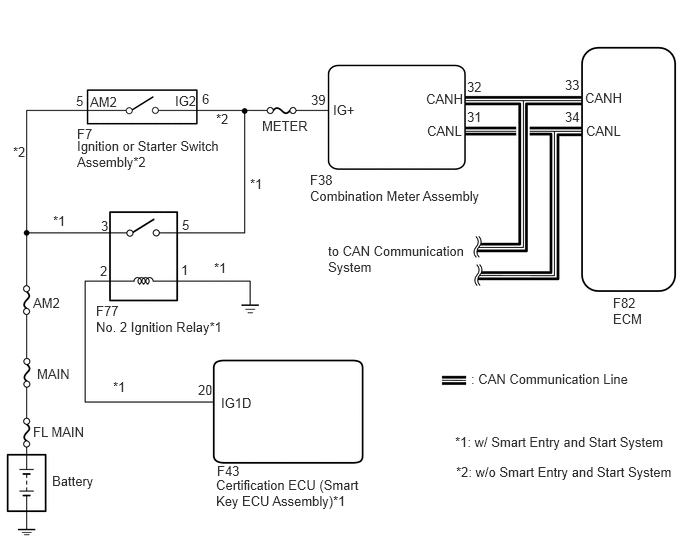
A301481E01
6.385,3.24 6.844,3.438 0.458,0.198 10 false ECM 6.104,1.281 6.563,1.479 0.458,0.198 10 false CANL 6.094,0.938 6.552,1.135 0.458,0.198 10 false CANH 0.802,1.438 2.375,1.938 1.573,0.5 10 false Ignition or Starter Switch Assembly*2 2.729,1.229 3.302,1.49 0.573,0.26 10 false METER 0.802,1.313 1.375,1.573 0.573,0.26 10 false F7 1,3.323 2.385,3.719 1.385,0.396 10 false No. 2 Ignition Relay*1 1,3.156 1.573,3.417 0.573,0.26 10 false F77 3.469,1.063 4.042,1.323 0.573,0.26 10 false IG+ 0.938,0.979 1.51,1.24 0.573,0.26 10 false AM2 0.344,3.073 0.917,3.333 0.573,0.26 10 false AM2 0.385,3.813 0.958,4.073 0.573,0.26 10 false MAIN 0.542,4.927 1.115,5.188 0.573,0.26 10 false Battery 3.229,1.958 5.094,2.323 1.865,0.365 10 false Combination Meter Assembly 2.25,4.969 3.813,5.417 1.563,0.448 10 false Certification ECU (Smart Key ECU Assembly)*1 4.448,1.281 4.906,1.479 0.458,0.198 10 false CANL 4.438,0.948 4.896,1.146 0.458,0.198 10 false CANH 4.865,1.135 5.323,1.333 0.458,0.198 10 false 31 4.865,0.823 5.323,1.021 0.458,0.198 10 false 32 5.885,0.802 6.344,1 0.458,0.198 10 false 33 5.885,1.135 6.344,1.333 0.458,0.198 10 false 34 6.385,3.073 6.844,3.271 0.458,0.198 10 false F82 2.302,4.115 2.76,4.313 0.458,0.198 10 false IG1D 2.063,3.979 2.521,4.177 0.458,0.198 10 false 20 2.26,4.823 2.719,5.021 0.458,0.198 10 false F43 1.896,2.26 2.354,2.458 0.458,0.198 10 false 5 1.885,2.729 2.344,2.927 0.458,0.198 10 false 1 1.042,2.74 1.5,2.896 0.458,0.156 10 false 2 1.052,2.271 1.51,2.427 0.458,0.156 10 false 3 3.229,1.792 3.688,1.99 0.458,0.198 10 false F38 1.823,0.969 2.396,1.229 0.573,0.26 10 false IG2 3.24,0.958 3.698,1.156 0.458,0.198 10 false 39 2.104,0.948 2.563,1.146 0.458,0.198 10 false 6 0.792,0.969 1.25,1.167 0.458,0.198 10 false 5 1.177,3.948 1.635,4.146 0.458,0.198 10 false *1 2.229,2.708 2.688,2.906 0.458,0.198 10 false *1 2.604,1.833 3.063,2.031 0.458,0.198 10 false *1 0.552,2.219 1.01,2.417 0.458,0.198 10 false *1 0.135,1.5 0.594,1.698 0.458,0.198 10 false *2 2.25,1.156 2.708,1.354 0.458,0.198 10 false *2 4.74,4.521 7.094,4.729 2.354,0.208 10 false *1: w/ Smart Entry and Start System 4.75,4.833 7.146,5.021 2.396,0.188 10 false *2: w/o Smart Entry and Start System 3.417,2.531 4.875,3.021 1.458,0.49 10 false to CAN Communication System 4.906,3.865 6.615,4.208 1.708,0.344 10 false : CAN Communication Line 0.344,4.417 0.917,4.677 0.573,0.26 10 false FL MAIN

CAUTION / NOTICE / HINT

NOTICE:

Inspect the fuses for circuits related to this system before performing the following procedure.


PROCEDURE

1.CHECK THAT MIL IS ILLUMINATED
a.

Turn the ignition switch to ON.


b.

Check the illumination condition of the MIL.


Result:
Condition Proceed to
MIL remains illuminated A
MIL remains off (Does not illuminate at all) B
MIL illuminates for several seconds, but turns off after engine is started C


A

2.CHECK WHETHER DTC OUTPUT RECURS

B

4.CHECK THAT ENGINE STARTS

C

2.CHECK WHETHER DTC OUTPUT RECURS
a.

Connect the GTS to the DLC3.


b.

Turn the ignition switch to ON.


c.

Turn the GTS on.


d.

Enter the following menus: Powertrain / Engine and ECT / Trouble Codes.

Powertrain > Engine and ECT > Trouble Codes
50001 234

e.

Check if any DTCs have been detected. Note down any DTCs.


Result:
Result Proceed to
No DTC detected A
Any DTCs detected B


HINT:

Check for detected DTCs output from other ECUs which relate to the MIL.


A

3.CHECK CAN COMMUNICATION SYSTEM

B

REPAIR CIRCUITS INDICATED BY OUTPUT DTCS

3.CHECK CAN COMMUNICATION SYSTEM
a.

Check if CAN communication system DTCs are output.

Click herePower Source / Network>NETWORKING>CAN COMMUNICATION SYSTEM>DIAGNOSIS SYSTEM


Result:
Result Proceed to
DTCs are not output. A
DTCs are output. B


A

B

4.CHECK THAT ENGINE STARTS
a.

Turn the ignition switch to ON.


b.

Start the engine.


Result:
Result Proceed to
Engine starts A
Engine does not start* B


HINT:

*: The GTS cannot communicate with the ECM.


A

B