RM30M0E
_59
Vehicle Exterior
_017126
LIGHTING (EXT)
_0090942
LIGHTING SYSTEM
U
LIGHTING (EXT) LIGHTING SYSTEM TERMINALS OF ECU
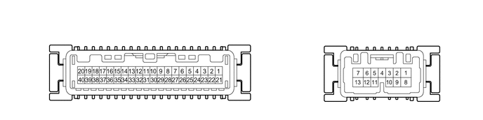
CHECK COMBINATION METER ASSEMBLY
5.365,0.229 5.896,0.552
0.531,0.323
5.51,0.313 5.969,0.51
0.458,0.198
10
false
F39
a.
Disconnect the F39 combination meter assembly connector.
b.
Measure the voltage according to the value(s) in the table below.
| Terminal No. (Symbol) | Wiring Color | Terminal Description | Condition | Specified Condition |
|---|---|---|---|---|
| F39-1 (B) - Body ground | B - Body ground | Battery power supply | Always | 11 to 14 V |
If the result is not as specified, there may be a malfunction in the wire harness.
c.
Reconnect the F39 combination meter assembly connector.
d.
Measure the voltage according to the value(s) in the table below.
| Terminal No. (Symbol) | Wiring Color | Terminal Description | Condition | Specified Condition |
|---|---|---|---|---|
| F39-3 (HAZ) - Body ground | P - Body ground | Hazard warning signal switch input | Hazard warning signal switch off | 11 to 14 V |
| Hazard warning signal switch on | Below 1 V | |||
| F39-9 (ER) - Body ground | L - Body ground | Turn signal switch right signal input | Ignition switch ON, turn signal switch in neutral position | 11 to 14 V |
| Ignition switch ON, turn signal switch in right turn position | Below 1 V | |||
| F39-10 (EL) - Body ground | GR - Body ground | Turn signal switch left signal input | Ignition switch ON, turn signal switch in neutral position | 11 to 14 V |
| Ignition switch ON, turn signal switch in left turn position | Below 1 V |
If the result is not as specified, the combination meter assembly may be malfunctioning.