1NZ-FE ENGINE MECHANICAL CYLINDER HEAD REPLACEMENT
PROCEDURE

 11122
1.REMOVE INTAKE VALVE GUIDE BUSH
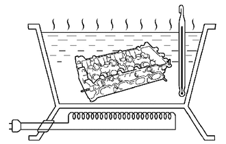
Heat the cylinder head sub-assembly to 80 to 100°C (176 to 212°F).
- CAUTION:
-
Make sure not to burn yourself.
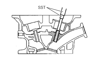
Using SST and a hammer, tap out the intake valve guide bush.
- SST
- 09201-10000 (09201-01050)
09950-70010 (09951-07100)
11126
2.REMOVE EXHAUST VALVE GUIDE BUSH
Heat the cylinder head sub-assembly to 80 to 100°C (176 to 212°F).
- CAUTION:
-
Make sure not to burn yourself.
Using SST and a hammer, tap out the exhaust valve guide bush.
- SST
- 09201-10000 (09201-01050)
09950-70010 (09951-07100)
11122
3.INSTALL INTAKE VALVE GUIDE BUSH
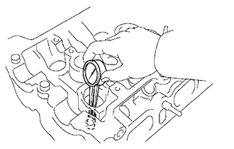
Using a caliper gauge, measure the intake valve guide bush bore diameter of the cylinder head sub-assembly.
- Inside diameter:
9.685 to 9.706 mm (0.3813 to 0.3821 in.)
If the intake valve guide bush bore diameter of the cylinder head sub-assembly is greater than 9.706 mm (0.3821 in.), machine the intake valve guide bush bore to the dimension of 9.735 to 9.755 mm (0.3833 to 0.3841 in.).
| Bushing bore diameter
mm (in.) |
Bushing size |
|---|---|
| 9.685 to 9.706
(0.3813 to 0.3821) |
STD |
| 9.735 to 9.755
(0.3833 to 0.3841) |
O/S 0.05 |
Heat the cylinder head sub-assembly to 80 to 100°C (176 to 212°F).
- CAUTION:
-
Make sure not to burn yourself.
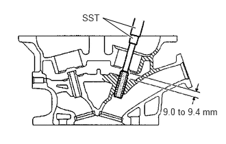
Using SST and a hammer, tap a new intake valve guide bush in to the specified protrusion height.
- SST
- 09201-10000 (09201-01050)
09950-70010 (09951-07100)
- Protrusion height:
9.0 to 9.4 mm (0.354 to 0.370 in.)
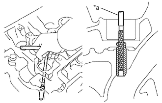
| *a | Sharp 5 mm Reamer |
Using a sharp 5 mm reamer, ream the intake valve guide bush to obtain the standard oil clearance between the intake valve guide bush and valve stem.
- Standard oil clearance:
0.025 to 0.060 mm (0.0010 to 0.0024 in.)
11126
4.INSTALL EXHAUST VALVE GUIDE BUSH
Using a caliper gauge, measure the exhaust valve guide bush bore diameter of the cylinder head sub-assembly.
- Inside diameter:
9.685 to 9.706 mm (0.3813 to 0.3821 in.)
If the exhaust valve guide bush bore diameter of the cylinder head sub-assembly is greater than 9.706 mm (0.3821 in.), machine the exhaust valve guide bush bore to the dimension of 9.735 to 9.755 mm (0.3833 to 0.3841 in.)
| Bushing bore diameter
mm (in.) |
Bushing size |
|---|---|
| 9.685 to 9.706
(0.3813 to 0.3821) |
STD |
| 9.735 to 9.755
(0.3833 to 0.3841) |
O/S 0.05 |
Heat the cylinder head sub-assembly to 80 to 100°C (176 to 212°F).
- CAUTION:
-
Make sure not to burn yourself.
Using SST and a hammer, tap a new exhaust valve guide bush in to the specified protrusion height.
- SST
- 09201-10000 (09201-01050)
09950-70010 (09951-07100)
- Protrusion height:
9.0 to 9.4 mm (0.354 to 0.370 in.)
Using a sharp 5 mm reamer, ream the exhaust valve guide bush to obtain the standard oil clearance between the exhaust valve guide bush and valve stem.
- Standard oil clearance:
0.030 to 0.065 mm (0.0012 to 0.0026 in.)