1NZ-FE ENGINE MECHANICAL CYLINDER BLOCK DISASSEMBLY
PROCEDURE

 1.INSPECT CONNECTING ROD THRUST CLEARANCE
2.INSPECT CONNECTING ROD OIL CLEARANCE
3.REMOVE PISTON SUB-ASSEMBLY WITH CONNECTING ROD
Using a ridge reamer, remove all the carbon from the top of the cylinder.
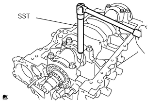
Using SST, remove the connecting rod bolts and connecting rod cap.
- SST
- 09205-16011
Push the piston, connecting rod and connecting rod bearing through the top of the cylinder block sub-assembly to remove them.
- HINT:
-
Keep the removed parts in the correct order so that they can be returned to their original locations when reassembled.
13041
4.REMOVE CONNECTING ROD BEARING
Remove the connecting rod bearings from the connecting rod and connecting rod cap.
- HINT:
-
Keep the removed parts in the correct order so that they can be returned to their original locations when reassembled.
5.INSPECT CRANKSHAFT THRUST CLEARANCE
6.INSPECT CRANKSHAFT OIL CLEARANCE
13411
7.REMOVE CRANKSHAFT
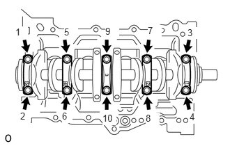
Using several steps, loosen and remove the 10 crankshaft bearing cap set bolts uniformly in the sequence shown in the illustration.
Remove the 5 crankshaft bearing caps and crankshaft.
11711
8.REMOVE CRANKSHAFT BEARING
Remove the 10 crankshaft bearings from the cylinder block sub-assembly and crankshaft bearing caps.
- HINT:
-
Keep the removed parts in the correct order so that they can be returned to their original locations when reassembled.
11791
9.REMOVE UPPER CRANKSHAFT THRUST WASHER
Remove the 2 upper crankshaft thrust washers from the cylinder block sub-assembly.
13011
10.REMOVE PISTON RING SET
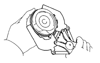
Using a piston ring expander, remove the No. 1 compression ring and No. 2 compression ring from the piston.
- HINT:
-
Keep the removed parts in the correct order so that they can be returned to their original locations when reassembled.
Remove the 2 side rails and oil ring from the piston by hand.
- HINT:
-
Keep the removed parts in the correct order so that they can be returned to their original locations when reassembled.
13101
11.REMOVE PISTON WITH PIN SUB-ASSEMBLY
Using SST, press the piston pin out of the piston.
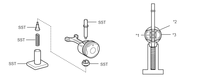
| *1 | Connecting Rod | *2 | Piston Pin |
| *3 | Piston | - | - |
- SST
- 09221-25026 (09221-00021, 09221-00030, 09221-00150, 09221-00090, 09221-00100)
- NOTICE:
-
Keep the pistons, piston pins, piston rings, connecting rods and connecting rod bearings in the correct order so that they can be returned to their original locations when reassembled.
11415
12.REMOVE CYLINDER BLOCK WATER DRAIN COCK SUB-ASSEMBLY
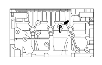
Using a 14 mm deep socket wrench, remove the cylinder block water drain cock sub-assembly from the cylinder block sub-assembly.
13.REMOVE STUD BOLT
Using an E5 and E7 "TORX" wrench, remove the 7 stud bolts from the cylinder block sub-assembly.
15100A
14.REMOVE OIL PUMP SET RING PIN
Remove the 2 oil pump set ring pins from the cylinder block sub-assembly.
11434C
15.REMOVE STRAIGHT PIN
Remove the 7 straight pins from the cylinder block sub-assembly.
13516B
16.REMOVE OIL JET
Remove the oil jet from the cylinder block sub-assembly.