1NZ-FE ENGINE CONTROL IGNITION COIL AND SPARK PLUG INSTALLATION
PROCEDURE

 1.INSTALL PLUG CAP
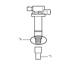
| *1 | Plug Cap |
| *a | Plug Cap Fitting |
Clean the plug cap fitting of the No. 1 ignition coil.
- NOTICE:
-
Foreign matter adhering to the plug cap fitting can cause high-voltage electrical leakage.
Install a new plug cap to the No. 1 ignition coil.
- NOTICE:
- ·
Make sure the plug cap is fully inserted all the way to section A.
·When installing the plug cap, do not allow any foreign matter to adhere to the plug cap or plug cap fitting.
·When installing the plug cap, be careful not to damage the plug cap or plug cap fitting.
- HINT:
-
Allowing any foreign matter to adhere to the contact surfaces, or damaging the plug cap or fitting, can result in high-voltage electrical leakage.
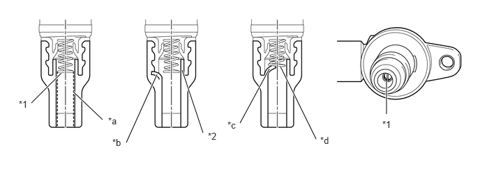
| *1 | Spring | *2 | Inner Tube |
| *a | Area with Talc Applied | *b | Inner Tube is Pinched |
| *c | Inner Tube is Deformed | *d | Spring is Pinched |
- NOTICE:
- ·
When installing the plug cap, make sure not to pinch the inner tube.
·When installing the plug cap, make sure the spring is not pinched by the inner tube.
·After installing the plug cap, look through the tip of the plug cap into the interior and check that the inner tube and spring are not pinched or deformed.
- HINT:
-
If there is any pinching or deformation of the inner tube or spring, the electrical connection between the spring and spark plug terminal will be poor, which can result in engine misfires and DTC output.
- NOTICE:
-
When installing the plug cap, do not remove the talc (white powder) that has been applied to the inner surfaces of the plug cap.
- HINT:
-
If the amount of talc applied is insufficient, this may cause the plug cap and spark plug to become stuck together in the future.
- NOTICE:
-
When installing the plug cap or spark plug, do not apply oil or grease to the engagement surfaces of the plug cap or spark plug.
- HINT:
-
Applying any oil or grease can cause the plug cap to deteriorate, resulting in high-voltage electrical leakage.
19100P
2.INSTALL SPARK PLUG
Using a 16 mm spark plug wrench, install the 4 spark plugs to the cylinder head sub-assembly.
- Torque:
- 18 N*m (184 kgf*cm, 13 ft.*lbf)
- NOTICE:
-
If a component has been dropped or subjected to a strong impact, replace the spark plug.
19500D
3.INSTALL NO. 1 IGNITION COIL
Install the 4 No. 1 ignition coils to the cylinder head cover sub-assembly with the 4 bolts.
- Torque:
- 9.0 N*m (92 kgf*cm, 80 in.*lbf)
- NOTICE:
-
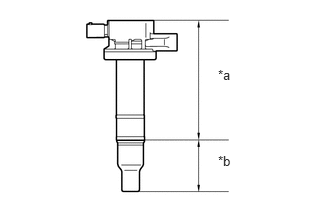 2.271,1.594 2.469,1.792 0.198,0.198 10 false *b 2.271,0.698 2.469,0.896 0.198,0.198 10 false *a
*a Body *b Cap
-
If the body or cap of the No. 1 ignition coil is dropped or subjected to a strong impact, replace the No. 1 ignition coil with a new one.
Connect the 4 No. 1 ignition coil connectors.
11212
4.INSTALL NO. 2 CYLINDER HEAD COVER