1NZ-FE INTAKE / EXHAUST EXHAUST MANIFOLD INSTALLATION
PROCEDURE

 17141
1.INSTALL EXHAUST MANIFOLD
Install a new exhaust manifold to head gasket to the cylinder head sub-assembly.
Temporarily install the exhaust manifold to the cylinder head sub-assembly with the 3 bolts and 2 nuts.
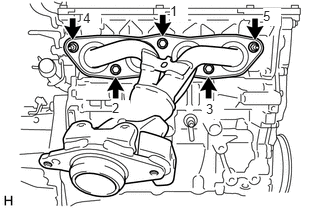
Tighten the 3 bolts and 2 nuts in the order shown in the illustration.
- Torque:
- 27 N*m (275 kgf*cm, 20 ft.*lbf)
25591
2.INSTALL MANIFOLD SUPPORT BRACKET
Temporarily install the manifold support bracket to the exhaust manifold and cylinder block sub-assembly with the 3 bolts.
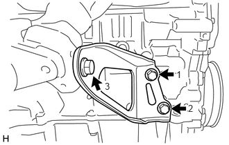
Tighten the 3 bolts in the order shown in the illustration.
- Torque:
- 44 N*m (449 kgf*cm, 32 ft.*lbf)
17410
3.INSTALL FRONT EXHAUST PIPE ASSEMBLY
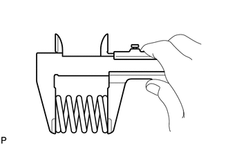
Using a vernier caliper, measure the free length of the compression spring.
- Free Length of Compression Spring:
Compression Spring Standard Length Minimum Length Front Side 42 mm (1.65 in.) 40.5 mm (1.59 in.) Rear Side 40 mm (1.57 in.) 38.5 mm (1.52 in.)
If the length is not as specified, replace the compression spring.
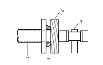
| *1 | Exhaust Manifold |
| *2 | Exhaust Pipe Gasket |
| *a | Wooden Block |
| *b | Plastic Hammer |
Using a plastic hammer and a wooden block, tap in a new exhaust pipe gasket until its surface is flush with the exhaust manifold.
- NOTICE:
- ·
Install the exhaust pipe gasket in the correct direction.
·Do not reuse the exhaust pipe gasket.
·Do not damage the exhaust pipe gasket by dropping it, etc.
·Do not damage the outer surface of the exhaust pipe gasket.
·Do not push in the exhaust pipe gasket with the front exhaust pipe assembly when connecting it.
| *1 | Front Exhaust Pipe Assembly |
| *2 | Exhaust Pipe Gasket |
| *a | Wooden Block |
| *b | Plastic Hammer |
Using a plastic hammer and a wooden block, tap in a new exhaust pipe gasket until its surface is flush with the front exhaust pipe assembly.
- NOTICE:
- ·
Install the exhaust pipe gasket in the correct direction.
·Do not reuse the exhaust pipe gasket.
·Do not damage the exhaust pipe gasket by dropping it, etc.
·Do not damage the outer surface of the exhaust pipe gasket.
·Do not push in the exhaust pipe gasket with the tail exhaust pipe assembly when connecting it.
Connect the 3 exhaust pipe supports to install the front exhaust pipe assembly to the vehicle.
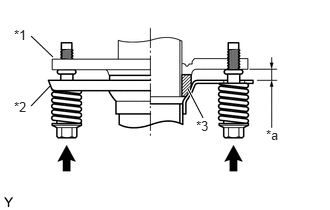
| *1 | Exhaust Manifold |
| *2 | Front Exhaust Pipe Assembly |
| *3 | Exhaust Pipe Gasket |
| *a | Space between flanges: 8.5 mm (0.335 in.) |
Connect the front exhaust pipe sub-assembly to the exhaust manifold with the 2 compression springs and 2 bolts.
- Torque:
43 N*m (440 kgf*cm, 32 ft.*lbf)
- NOTICE:
-
After the installation, check that the gaps between the flanges of the exhaust manifold and front exhaust pipe assembly are consistent front-to-rear and left-to-right.
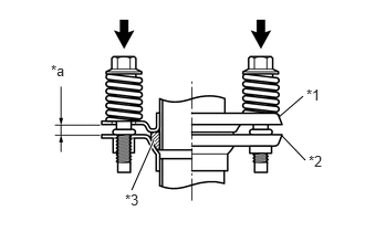
| *1 | Front Exhaust Pipe Assembly |
| *2 | Tail Exhaust Pipe Assembly |
| *3 | Exhaust Pipe Gasket |
| *a | Space between flanges: 6.5 mm (0.256 in.) |
Connect the front exhaust pipe assembly to the tail exhaust pipe assembly with the 2 compression springs and 2 bolts.
- Torque:
43 N*m (440 kgf*cm, 32 ft.*lbf)
- NOTICE:
-
After the installation, check that the gaps between the flanges of the tail exhaust pipe assembly and front exhaust pipe assembly are consistent front-to-rear and left-to-right.
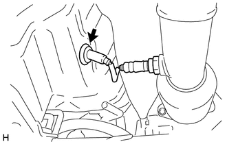
Pass the connector through the hole to the inside of the vehicle and install the heated oxygen sensor wire grommet.
Connect the heated oxygen sensor connector.
Return the front floor carpet assembly to its normal position and engage it.
Install the clip to the front floor carpet assembly.
57533B
4.INSTALL FRONT FLOOR CENTER BRACE
Install the front floor center brace to the vehicle with the 4 bolts.
- Torque:
- 30.1 N*m (307 kgf*cm, 22 ft.*lbf)
89465
5.INSTALL HEATED OXYGEN SENSOR (for Sensor 1)
58910C
6.INSTALL REAR CONSOLE BOX ASSEMBLY
7.INSPECT FOR EXHAUST GAS LEAK