RM30M0E
_54
Brake
_017099
BRAKE SYSTEM (OTHER)
_0092760
VACUUM SWITCHING VALVE
G
BRAKE SYSTEM (OTHER) VACUUM SWITCHING VALVE INSPECTION
PROCEDURE

 25860
1.INSPECT VACUUM SWITCHING VALVE ASSEMBLY
a.
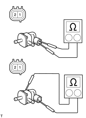
Check the vacuum switching valve assembly for an open circuit.
i.
1.831,0.87 1.968,1.033
0.137,0.163
10
2
1.473,2.029 1.604,2.182
0.131,0.153
10
1
1.566,1.597 1.858,1.057
false
1.532,1.694 1.533,2.021
false
1.488,4.264 1.619,4.417
0.131,0.153
10
1
1.537,3.997 1.54,4.266
false
1.819,3.188 1.956,3.351
0.137,0.163
10
2
1.555,3.916 1.847,3.376
false
0.147,0.095 0.313,0.245
0.166,0.15
10
*a
0.147,2.224 0.313,2.375
0.166,0.15
10
*a
| *a | Component without harness connected
(Vacuum Switching Valve Assembly) |
Measure the resistance according to the value(s) in the table below.
- Standard Resistance:
Tester Connection Condition Specified Condition 1 - 2 20°C (68°F) 23 to 26 Ω 1 - Body ground Always 10 MΩ or higher 2 - Body ground Always 10 MΩ or higher
If the result is not as specified, replace the vacuum switching valve assembly.
b.
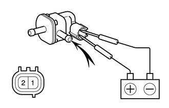
Check the operation of the vacuum switching valve assembly.
i.
1.396,1.333 1.396,0.833
false
0.656,0.99 0.667,0.708
true
0.094,1.167 0.302,1.365
0.208,0.198
10
false
*a
1.365,1.365 1.677,1.563
0.313,0.198
10
false
*b
0.615,1.021 0.927,1.219
0.313,0.198
10
false
*c
1.813,1.365 2.125,1.563
0.313,0.198
10
false
*d
| *a | Component without harness connected
(Vacuum Switching Valve Assembly) |
| *b | Port E |
| *c | Port F |
| *d | Air |
Apply battery voltage between the terminals of the vacuum switching valve assembly and check that the following occurs when blowing air into port E.
- OK:
Measurement Condition Specified Condition Battery voltage applied between terminals 1 and 2 Air flows from port F. Battery voltage not applied between terminals 1 and 2 Air does not flow.
If the result is not as specified, replace the vacuum switching valve assembly.