C54 MANUAL TRANSMISSION / TRANSAXLE INPUT SHAFT REASSEMBLY
PROCEDURE

 1. PRECAUTION
- NOTICE:
- ·
All disassembled parts should be cleaned before reassembly.
·Coat all of the sliding and rotating surfaces with gear oil before reassembly, and check that they move smoothly after reassembly.
33364
2.INSTALL NO. 2 TRANSMISSION HUB SLEEVE
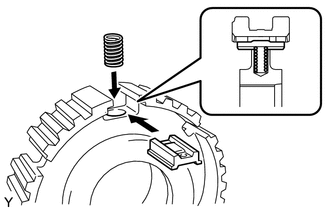
Coat the No. 2 transmission hub sleeve with gear oil.
Install the 3 synchromesh shifting key springs and the 3 synchromesh shifting keys to the No. 2 transmission clutch hub.
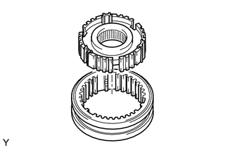
Install the No. 2 transmission clutch hub to the No. 2 transmission hub sleeve.
- NOTICE:
-
Position the No. 2 transmission hub sleeve and the No. 2 transmission clutch hub correctly as shown in the illustration.
33333A
3.INSTALL 3RD GEAR NEEDLE ROLLER BEARING
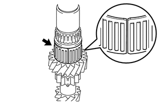
Coat the 3rd gear needle roller bearing with gear oil and install it to the input shaft.
33333
4.INSTALL 3RD GEAR
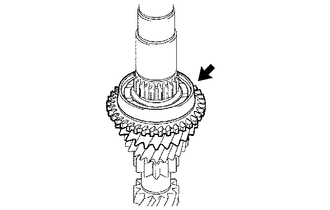
Coat the 3rd gear with gear oil and install it to the input shaft.
33368G
5.INSTALL 3RD GEAR SYNCHRONIZER RING
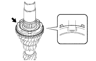
| *a | Key Position |
| *b | for 3rd Gear |
Coat the 3rd gear synchronizer ring with gear oil and install it to the 3rd gear.
33362
6.INSTALL NO. 2 TRANSMISSION CLUTCH HUB
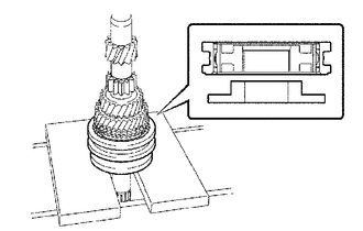
Using SST and a press, install the No. 2 transmission clutch hub to the input shaft.
- SST
- 09316-60011 (09316-00021)
- NOTICE:
-
Fit the synchromesh shifting keys into the grooves of the synchronizer ring correctly.
Select a new No. 2 clutch hub setting shaft snap ring that will allow minimum axial play.
- Standard clearance:
0.1 mm (0.00394 in.) or less
- Snap Ring Thickness:
Part No. Mark Thickness
mm (in.)90520-27046 0 2.30 (0.0906) 90520-27047 1 2.36 (0.0929) 90520-27048 2 2.42 (0.0953) 90520-27049 3 2.48 (0.0976) 90520-27050 4 2.54 (0.1000) 90520-27051 5 2.60 (0.1024)
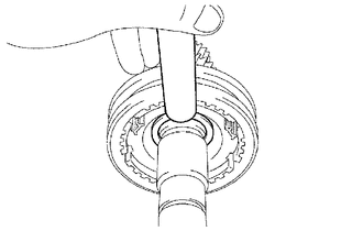
Using a brass bar and a hammer, install the No. 2 clutch hub setting shaft snap ring to the input shaft.
- NOTICE:
-
Do not expand the No. 2 clutch hub setting shaft snap ring excessively.
33368H
7.INSTALL 4TH GEAR SYNCHRONIZER RING
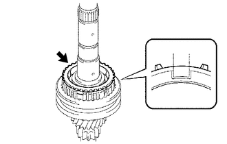
| *a | Key Position |
| *b | for 4th Gear |
Coat the 4th gear synchronizer ring with gear oil and install it to the No. 2 transmission clutch hub.
33334A
8.INSTALL 4TH GEAR NEEDLE ROLLER BEARING
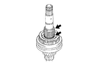
Coat the 4th gear needle roller bearing and the 4th gear bearing spacer with gear oil and install them to the input shaft.
33334
9.INSTALL 4TH GEAR
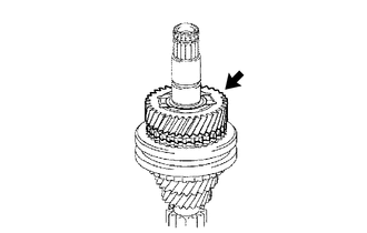
Coat the 4th gear with gear oil and install it to the input shaft.
33311E
10.INSTALL INPUT SHAFT REAR RADIAL BALL BEARING
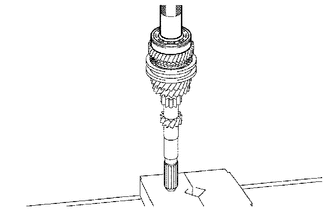
Using SST and a press, install the input shaft rear radial ball bearing to the input shaft.
- SST
- 09608-04031
Select a new input shaft rear bearing shaft snap ring that will allow minimum axial play.
- Standard clearance:
0.1 mm (0.00394 in.) or less
- Snap Ring Thickness:
Part No. Mark Thickness
mm (in.)90520-22006 A 2.29 (0.0902) 90520-22007 B 2.35 (0.0925) 90520-22008 C 2.41 (0.0949) 90520-22009 D 2.47 (0.0972) 90520-22010 E 2.53 (0.0996) 90520-22011 F 2.59 (0.1020)
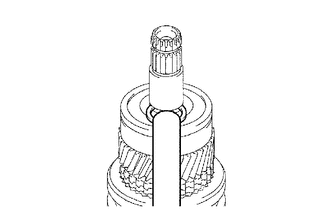
Using a brass bar and a hammer, install the input shaft rear bearing shaft snap ring to the input shaft.
- NOTICE:
- ·
Do not damage the journal surface of the input shaft rear bearing shaft snap ring.
·Do not expand the input shaft rear bearing shaft snap ring excessively.
11.INSPECT 3RD GEAR RADIAL CLEARANCE
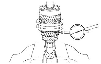
Using a dial indicator, measure the 3rd gear radial clearance.
- Standard clearance:
0.015 to 0.058 mm (0.000591 to 0.00228 in.)
- Maximum clearance:
0.058 mm (0.00228 in.)
If the clearance exceeds the maximum, replace the 3rd gear, 3rd gear needle roller bearing or input shaft.
12.INSPECT 4TH GEAR RADIAL CLEARANCE
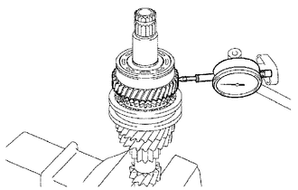
Using a dial indicator, measure the 4th gear radial clearance between the gear and input shaft.
- Standard clearance:
0.009 to 0.050 mm (0.000355 to 0.00196 in.)
- Maximum clearance:
0.050 mm (0.00196 in.)
If the clearance exceeds the maximum, replace the 4th gear, 4th gear needle roller bearing or input shaft.
13.INSPECT 3RD GEAR THRUST CLEARANCE
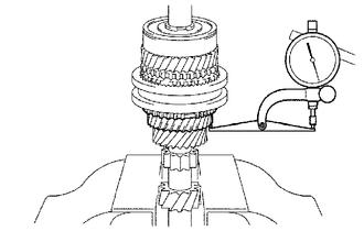
Using a dial indicator, measure the 3rd gear thrust clearance.
- Standard clearance:
0.10 to 0.35 mm (0.00394 to 0.0137 in.)
- Maximum clearance:
0.35 mm (0.0137 in.)
If the clearance exceeds the maximum, replace the No. 2 transmission clutch hub, 3rd gear or input shaft.
14.INSPECT 4TH GEAR THRUST CLEARANCE
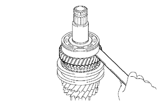
Using a feeler gauge, measure the 4th gear thrust clearance.
- Standard clearance:
0.10 to 0.55 mm (0.00394 to 0.0216 in.)
- Maximum clearance:
0.55 mm (0.0216 in.)
If the clearance exceeds the maximum, replace the No. 2 transmission clutch hub, 4th gear or input shaft rear radial ball bearing.