K411 CVT SHIFT LEVER REASSEMBLY
PROCEDURE

 33866
1.INSTALL NO. 1 SHIFT LOCK RELEASE SPRING
Install the No. 1 shift lock release spring to the No. 1 shift lock release button.
33563
2.INSTALL NO. 1 SHIFT LOCK RELEASE BUTTON
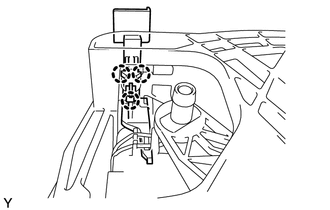
Engage the 3 claws to install the No. 1 shift lock release button to the shift lock control unit assembly.
35974
3.INSTALL LOWER POSITION INDICATOR HOUSING
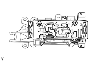
Engage the 4 claws to install the lower position indicator housing to the shift lock control unit assembly.
35976
4.INSTALL NO. 2 POSITION INDICATOR SLIDE COVER
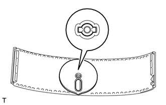
Align the cutouts on the shank of the No. 2 position indicator slide cover and No. 1 position indicator slide cover, and install the No. 2 position indicator slide cover to the No. 1 position indicator slide cover.
35975
5.INSTALL NO. 1 POSITION INDICATOR SLIDE COVER
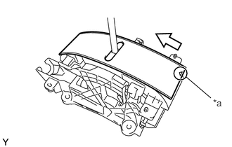
| *a | Alignment Mark |

|
Front Side of Vehicle |
Install the No. 1 position indicator slide cover to the lower position indicator housing.
- NOTICE:
-
Install the position indicator slide cover so that its alignment mark points to the front of the vehicle.
35971E
6.INSTALL POSITION INDICATOR HOUSING
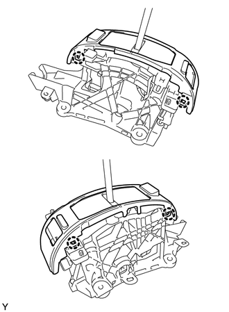
Engage the 4 claws to install the position indicator housing to the lower position indicator housing.
33866
7.INSTALL NO. 2 SHIFT LOCK RELEASE SPRING
Install the No. 2 shift lock release spring to the No. 2 shift lock release button.
33563
8.INSTALL NO. 2 SHIFT LOCK RELEASE BUTTON
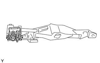
Engage the 2 claws to install the No. 2 shift lock release button to the position indicator light housing.
33502S
9.INSTALL SHIFT LOCK RELEASE BUTTON COVER
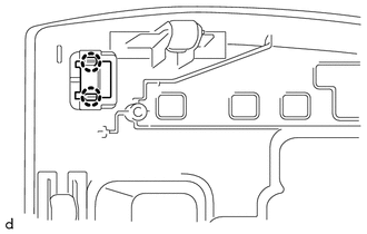
Engage the 2 claws to install the shift lock release button cover to the upper position indicator housing.
35921
10.INSTALL CONTROL POSITION INDICATOR PLATE
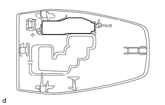
Install the control position indicator plate to the upper position indicator housing.
35961
11.INSTALL POSITION INDICATOR LIGHT HOUSING
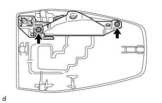
Install the position indicator light housing to the upper position indicator housing with the 2 screws.
35906
12.INSTALL INDICATOR LIGHT WIRE SUB-ASSEMBLY (for LHD)
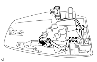
Turn the indicator light wire sub-assembly clockwise and install it to the position indicator light housing.
Engage the 4 clamps to install the indicator light wire sub-assembly to the position indicator light housing and upper position indicator housing.
35906
13.INSTALL INDICATOR LIGHT WIRE SUB-ASSEMBLY (for RHD)
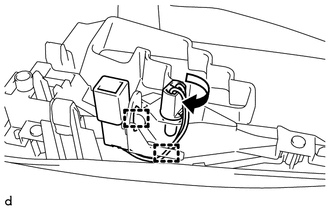
Turn the indicator light wire sub-assembly clockwise and install it to the position indicator light housing.
Engage the 2 clamps to install the indicator light wire sub-assembly to the position indicator light housing.