1NR-FE ENGINE MECHANICAL REAR CRANKSHAFT OIL SEAL INSTALLATION
CAUTION / NOTICE / HINT
PROCEDURE

 11401L
1.INSTALL REAR ENGINE OIL SEAL
Remove any old packing material and be careful not to drop any oil on the contact surfaces of the cylinder block sub-assembly and oil pan sub-assembly.
- NOTICE:
-
Be careful not to drop any oil on the contact surfaces of the oil pan sub-assembly and cylinder block sub-assembly.
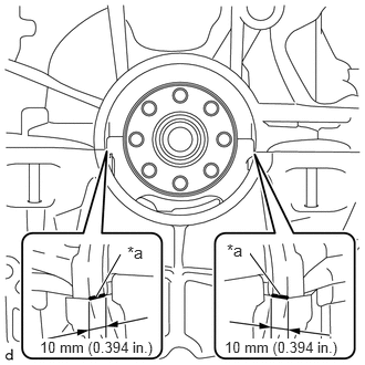
| *a | Seal Packing |
Apply seal packing in a continuous line as shown in the illustration.
- Seal packing:
Toyota Genuine Seal Packing Black, Three Bond 1207B or equivalent
- Seal diameter:
3.0 mm (0.118 in.)
- NOTICE:
- ·
Remove any oil from the contact surfaces.
·Install a new rear engine oil seal within 3 minutes of applying seal packing.
·Do not start the engine for at least 2 hours after installation.
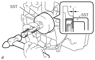
Using SST and a hammer, tap in a new rear engine oil seal until its surface is flush with the cylinder block sub-assembly and oil pan sub-assembly.
- SST
- 09223-56010
- Rear engine oil seal tap in depth:
-0.5 to 0.5 mm (-0.0197 to 0.0197 in.)
- NOTICE:
- ·
Make sure there is no foreign matter on the lip of the rear engine oil seal.
- ·
Make sure there is no oil or grease on the outer circumference of the rear engine oil seal.
- ·
Do not press in the rear engine oil seal at an angle.
- ·
Wipe off extra grease from the crankshaft.
32101
2.INSTALL DRIVE PLATE AND RING GEAR SUB-ASSEMBLY (for CVT)
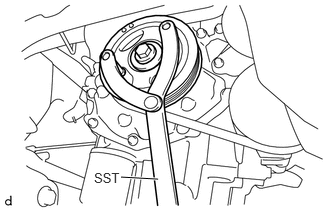
Using SST, hold the crankshaft pulley.
- SST
- 09960-10010 (09962-01000, 09963-01000)
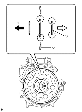
| *1 | Front Drive Plate Spacer (Reversible) |
| *2 | Drive Plate and Ring Gear Sub-assembly |
| *3 | Rear Drive Plate Spacer |

|
Engine Side |

|
Transaxle Side |
Install the front drive plate spacer, drive plate and ring gear sub-assembly, and rear drive plate spacer to the crankshaft.
- NOTICE:
-
As the drive plate and ring gear sub-assembly and the rear drive plate spacer are not reversible, be sure to install them so that they are facing in the direction shown in the illustration.
- HINT:
-
The front drive plate spacer is reversible.
Clean the 8 bolts and their holes.
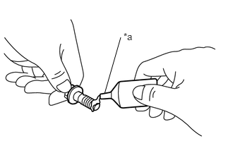
| *a | Adhesive |
Apply adhesive to 2 or 3 threads at the end of each of the 8 bolts.
- Adhesive:
Toyota Genuine Adhesive 1324, Three Bond 1324 or equivalent
- NOTICE:
-
To prevent contamination by foreign matter, install immediately after applying adhesive.
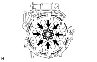
Install and uniformly tighten the 8 bolts in several steps, in the sequence shown in the illustration.
- Torque:
- 88 N*m (897 kgf*cm, 65 ft.*lbf)
- NOTICE:
-
Do not start the engine for at least 1 hour after installing the drive plate and ring gear sub-assembly.
13405
3.INSTALL FLYWHEEL SUB-ASSEMBLY (for Manual Transaxle)
Using SST, hold the crankshaft pulley.
- SST
- 09960-10010 (09962-01000, 09963-01000)
Install the flywheel sub-assembly to the crankshaft.
Clean the 8 bolts and their holes.
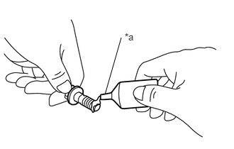
| *a | Adhesive |
Apply adhesive to 2 or 3 threads at the end of each of the 8 bolts.
- Adhesive:
Toyota Genuine Adhesive 1324, Three Bond 1324 or equivalent
- NOTICE:
-
To prevent contamination by foreign matter, install immediately after applying adhesive.
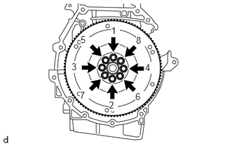
Install and uniformly tighten the 8 bolts in several steps, in the sequence shown in the illustration.
- Torque:
- 78 N*m (795 kgf*cm, 58 ft.*lbf)
- NOTICE:
-
Do not start the engine for at least 1 hour after installing the flywheel sub-assembly.
31250
4.INSTALL CLUTCH DISC ASSEMBLY (for Manual Transaxle)
31210
5.INSTALL CLUTCH COVER ASSEMBLY (for Manual Transaxle)
31210
6.INSPECT AND ADJUST CLUTCH COVER ASSEMBLY (for Manual Transaxle)
30400
7.INSTALL CONTINUOUSLY VARIABLE TRANSAXLE ASSEMBLY (for CVT)
30300
8.INSTALL MANUAL TRANSAXLE ASSEMBLY (for Manual Transaxle)
9.INSPECT FOR ENGINE OIL LEAK