RM30M0E
_51
Engine / Hybrid System
_053933
2NR-FE ENGINE MECHANICAL
_0262439
CYLINDER BLOCK
A
2NR-FE ENGINE MECHANICAL CYLINDER BLOCK REPLACEMENT
PROCEDURE

 1.REPLACE RING PIN
- NOTICE:
-
It is not necessary to remove the ring pins unless they are being replaced.
a.
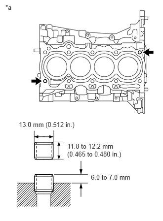
Remove the 2 ring pins from the cylinder block sub-assembly.
b.
0.115,0.073 0.427,0.229
0.313,0.156
10
false
*a
0.396,2.552 1.646,2.75
1.25,0.198
10
false
13.0 mm (0.512 in.)
1.417,3.01 2.604,3.427
1.188,0.417
10
false
11.8 to 12.2 mm (0.465 to 0.480 in.)
1.917,3.667 2.906,3.875
0.99,0.208
10
false
6.0 to 7.0 mm
| *a | Upper Side |
Using a plastic hammer, tap in 2 new ring pins to the cylinder block sub-assembly.
- Protrusion Height:
6.0 to 7.0 mm (0.237 to 0.275 in.)
2.REPLACE STRAIGHT PIN
- NOTICE:
-
It is not necessary to remove the straight pins unless they are being replaced.
a.
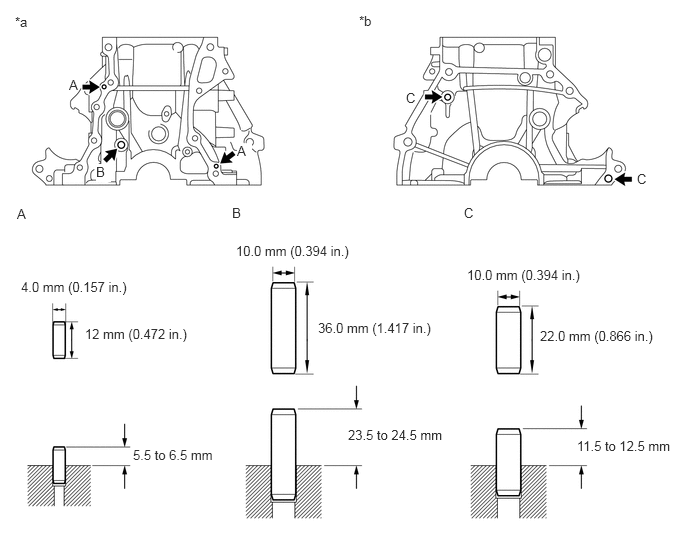
Remove the 5 straight pins from the cylinder block sub-assembly.
b.
Using a plastic hammer, tap in 5 new straight pins to the cylinder block sub-assembly.
0.156,0.146 0.469,0.302
0.313,0.156
10
false
*a
3.74,0.135 4.052,0.292
0.313,0.156
10
false
*b
0.719,0.802 0.875,0.99
0.156,0.188
10
false
A
1,1.708 1.156,1.896
0.156,0.188
10
true
B
2.469,1.49 2.625,1.677
0.156,0.188
10
true
A
4.229,0.938 4.385,1.125
0.156,0.188
10
false
C
6.635,1.781 6.792,1.969
0.156,0.188
10
false
C
0.177,2.146 0.333,2.333
0.156,0.188
10
false
A
2.417,2.135 2.573,2.323
0.156,0.188
10
false
B
4.833,2.135 4.99,2.323
0.156,0.188
10
false
C
0.219,2.906 1.552,3.365
1.333,0.458
10
false
4.0 mm (0.157 in.)
0.885,3.396 2.063,3.76
1.177,0.365
10
false
12 mm (0.472 in.)
2.458,2.531 3.865,2.875
1.406,0.344
10
false
10.0 mm (0.394 in.)
3.313,3.333 4.656,3.74
1.344,0.406
10
false
36.0 mm (1.417 in.)
5.625,3.417 6.906,3.594
1.281,0.177
10
false
22.0 mm (0.866 in.)
1.385,4.656 2.365,4.844
0.979,0.188
10
false
5.5 to 6.5 mm
3.625,4.448 4.698,4.635
1.073,0.188
10
false
23.5 to 24.5 mm
6.01,4.563 7.083,4.75
1.073,0.188
10
false
11.5 to 12.5 mm
4.865,2.781 6.302,3.135
1.438,0.354
10
false
10.0 mm (0.394 in.)
| *a | Front Side | *b | Rear Side |
- Protrusion Height:
Item Protrusion Height Pin A 5.5 to 6.5 mm (0.217 to 0.256 in.) Pin B 23.5 to 24.5 mm (0.925 to 0.965 in.) Pin C 11.5 to 12.5 mm (0.453 to 0.492 in.)