C50 MANUAL TRANSMISSION / TRANSAXLE SHIFT AND SELECT LEVER SHAFT(for 2NR-FE) REASSEMBLY
PROCEDURE

 1. PRECAUTION
- NOTICE:
- ·
All disassembled parts should be cleaned before reassembly.
·Coat all of the sliding and rotating surfaces with gear oil before reassembly, and check that they move smoothly after reassembly.
33528C
2.INSTALL CONTROL SHAFT COVER OIL SEAL
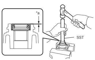
| *a | Drive in Depth |
Using SST and a hammer, install a new control shaft cover oil seal to the control shaft cover.
- SST
- 09950-60010 (09951-00280)
09950-70010 (09951-07150)
- Standard depth:
0 to 0.9 mm (0 to 0.0354 in.)
Coat the lip of the control shaft cover oil seal with MP grease.
33531B
3.INSTALL SHIFT AND SELECT LEVER SHAFT DUST BOOT
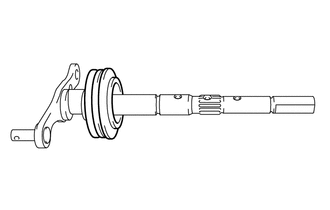
Install the shift and select lever shaft dust boot to the shift and select lever shaft.
33528B
4.INSTALL CONTROL SHAFT COVER
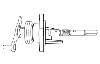
Install the control shaft cover to the shift and select lever shaft.
- NOTICE:
- ·
Do not damage the control shaft cover oil seal.
·Make sure that the control shaft cover dust boot is securely installed the groove of the shift and select lever shaft and control shaft cover.
33276H
5.INSTALL NO. 1 SELECT SPRING SEAT SHAFT SNAP RING
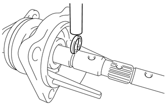
Coat the shift and select lever shaft with gear oil.
Using a brass bar and a hammer, install a new No. 1 select spring seat shaft snap ring to the shift and select lever shaft.
33256
6.INSTALL SELECT INNER LEVER
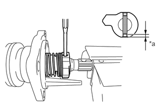
| *a | Drive in Depth |
Coat the No. 1 select spring seat with gear oil.
Using a 5 mm pin punch and a hammer, install the No. 1 select spring seat, compression spring, select inner lever and select inner lever slotted spring pin to the shift and select lever shaft.
- Driven in depth:
3.0 to 4.0 mm (0.119 to 0.157 in.)
33251A
7.INSTALL INNER NO. 1 SHIFT LEVER
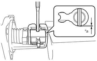
| *a | Drive in Depth |
Coat the shift interlock plate and inner No. 1 shift lever with gear oil.
Using a 5 mm pin punch and a hammer, install the shift interlock plate, inner No. 1 shift lever and inner No. 1 shift lever slotted spring pin to the shift and select lever shaft.
- Driven in depth:
-0.5 to 0.5 mm (-0.0196 to 0.0196 in.)
33252A
8.INSTALL INNER NO. 2 SHIFT LEVER
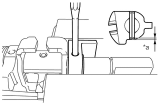
| *a | Drive in Depth |
Coat the inner No. 2 shift lever with gear oil.
Using a 5 mm pin punch and a hammer, install the inner No. 2 shift lever and inner No. 2 shift lever slotted spring pin to the shift and select lever shaft.
- Driven in depth:
1.0 to 2.0 mm (0.0394 to 0.0787 in.)
33277
9.INSTALL NO. 2 SELECT SPRING SEAT
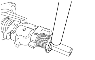
Coat the No. 2 select spring seat with gear oil.
Install the No. 2 select spring seat and compression spring to the shift and select lever shaft.
Using a brass bar and a hammer, install a new E-ring to the shift and select lever shaft.
33534F
10.INSTALL NO. 2 SELECTING BELLCRANK BUSH
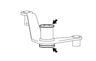
Install 2 new No. 2 selecting bellcrank bushes to the selecting bellcrank.
Coat the No. 2 selecting bellcrank bushes with MP grease.
33558
11.INSTALL NO. 2 SELECTING BELLCRANK DUST COVER
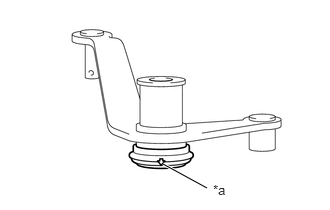
| *a | Arrow Mark |
Install the No. 2 selecting bellcrank dust cover to the selecting bellcrank.
- HINT:
-
Position the arrow mark as shown in the illustration.
33534E
12.INSTALL NO. 2 SELECTING BELLCRANK
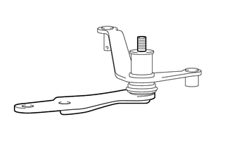
Install the selecting bellcrank support sub-assembly to the selecting bellcrank.
33534G
13.INSTALL NO. 2 SELECTING BELLCRANK PLATE WASHER
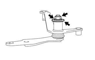
Install the No. 2 selecting bellcrank plate washer to the selecting bellcrank support sub-assembly with the washer and nut.
- Torque:
- 11.8 N*m (120 kgf*cm, 9 ft.*lbf)
33557A
14.INSTALL NO. 1 SELECTING BELLCRANK DUST COVER
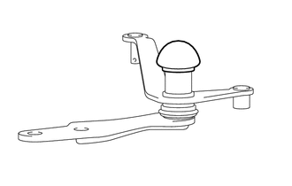
Install the No. 1 selecting bellcrank dust cover to the selecting bellcrank.