RM30M0E
_58
Vehicle Interior
_017118
HEATING / AIR CONDITIONING
_0086573
AIR CONDITIONING SYSTEM(for Automatic Air Conditioning System)
D
HEATING / AIR CONDITIONING AIR CONDITIONING SYSTEM(for Automatic Air Conditioning System) SYSTEM DESCRIPTION
FUNCTION OF MAIN COMPONENTS
a.
The main components of the air conditioning system have the following functions.
| Component | Function |
|---|---|
| Air Conditioning Control Assembly | Allows operation and adjustment of the air conditioning system via switches. |
| Air Conditioning Amplifier Assembly | Transmits and receives data to and from the switches and sensors, and controls the air conditioning system. |
| Cooler Compressor Assembly | A compact, lightweight, and low-noise 10-cylinder swash plate type cooler compressor is used. |
| Cooler Condenser Assembly | A multi-flow (MF)-IV sub-cool condenser is used to improve heat exchange efficiency. |
| Blower Motor with Fan Sub-assembly | The fan blades are thin, and improve air flow inside the blower fan, contributing to the reduction of noise. |
| Heater Radiator Assembly | A Straight Flow Aluminum-II (SFA-II) heater radiator is used for compactness and high performance. |
| No. 1 Cooler Evaporator Sub-assembly | A revolutionary super-slim structure (RS) evaporator is used for compactness. |
| No. 1 Cooler Thermistor | Detects the temperature of the cool air past the No. 1 cooler evaporator sub-assembly and transmits the data to the air conditioning amplifier assembly. |
| Thermistor Assembly | Detects ambient temperature and outputs it to the air conditioning amplifier assembly. |
| Cooler (Room Temperature Sensor) Thermistor | Detects room temperature and outputs it to the air conditioning amplifier assembly. |
| Cooler (Solar Sensor) Thermistor | Detects the changes in the amount of solar energy and outputs them to the air conditioning amplifier assembly. |
| Damper Servo Sub-assembly | Receives the input of the operation signals from the air conditioning amplifier assembly, operates the motor, and opens and closes the dampers. |
| No. 1 Pressure Switch*1 | Detects the refrigerant pressure and sends the data to the air conditioning amplifier assembly. |
| Air Conditioner Pressure Sensor*2 | |
| ECM | Transmits the air conditioning off request signal to the air conditioning amplifier assembly. |
*1: for 1NZ-FE or 2NZ-FE
*2: for 1NR-FE or 2NR-FE
SYSTEM CONTROL
a.
The air conditioning system has the following controls.
| Control | Outline | |
|---|---|---|
| Outlet Air Temperature Control | After receiving the signals from the sensors and the temperature control switching setting, it uses a prescribed formula to calculate the required outlet air temperature, and regulate the servo motors and the blower motor. This outlet temperature is required in order to maintain the set temperature in a stable manner. | |
| Blower Control | Manual Control | Set the blower speed according to operation of the blower switch. |
| Automatic Control | This function controls the operation of the blower motor with fan sub-assembly in accordance with the signals from the No. 1 cooler thermistor and the cooler (solar sensor) thermistor. In addition, it protects the blower motor control from the sudden drive current that occurs when the blower motor with fan sub-assembly is activated. | |
| Air Outlet Control | Manual Control | Changes the air outlet in accordance with the selected position of the mode select switch. |
| Automatic Control | Controls the air outlet mode to switch to FACE, BI-LEVEL and FOOT in accordance with the required outlet air temperature when the AUTO switch has been turned on. | |
| Compressor Control | When the AUTO switch is turned on, the magnetic clutch relay is activated automatically to engage the compressor.
When the defroster switch is turned on, the magnetic clutch relay is activated. |
|
| Rear Defogger Control | Refer to Rear Defogger System.
Click here(  ) |
|
| Diagnosis | A Diagnostic Trouble Code (DTC) is stored in memory when the air conditioning amplifier assembly detects a problem with the air conditioning system. | |
MODE POSITION AND DAMPER OPERATION
a.
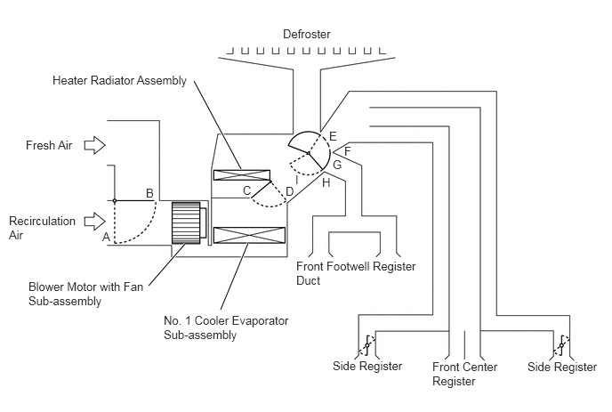
Mode Position and Damper Operation.
2.271,0.948 2.823,1.979
true
2.167,2.854 1.74,3.344
true
2.906,2.844 2.583,3.625
true
3.313,0.313 4.688,0.51
1.375,0.198
10
false
Defroster
0.302,1.615 1.677,1.813
1.375,0.198
10
false
Fresh Air
0.104,2.5 0.958,2.875
0.854,0.375
10
false
Recirculation Air
1.198,2.688 1.458,2.875
0.26,0.188
10
false
A
1.708,2.177 1.969,2.365
0.26,0.188
10
false
B
0.333,3.271 1.719,3.635
1.385,0.365
10
false
Blower Motor with Fan Sub-assembly
1.917,3.667 3.417,4.063
1.5,0.396
10
false
No. 1 Cooler Evaporator Sub-assembly
0.615,0.854 2.26,1.073
1.646,0.219
10
false
Heater Radiator Assembly
2.844,2.146 3.104,2.333
0.26,0.188
10
false
C
3.344,2.156 3.604,2.344
0.26,0.188
10
false
D
3.458,2.021 3.719,2.208
0.26,0.188
10
false
I
3.771,2.052 4.031,2.24
0.26,0.188
10
false
H
3.896,1.844 4.156,2.031
0.26,0.188
10
false
G
4.031,1.688 4.292,1.875
0.26,0.188
10
false
F
3.854,1.51 4.115,1.698
0.26,0.188
10
false
E
3.469,3.031 4.917,3.396
1.448,0.365
10
false
Front Footwell Register Duct
3.896,4.198 4.802,4.396
0.906,0.198
10
false
Side Register
6.177,4.208 7.083,4.406
0.906,0.198
10
false
Side Register
5.063,4.208 5.875,4.573
0.813,0.365
10
false
Front Center Register
| Control Damper | Operation Position | Damper Position | Operation |
|---|---|---|---|
| Air Inlet Control Damper | FRESH | A | Allows fresh air to enter. |
| RECIRCULATION | B | Causes internal air to recirculate. | |
| Air Mix Control Damper | MAX COLD to MAX HOT Temperature Setting | C - D | Varies the mixture ratio of warm air and cool air in order to regulate the temperature continuously between hot and cold. |
| Air Outlet Control Damper | FACE

|
E | Air blows out of the front center registers and side registers. In addition, air blows out slightly from the front footwell register ducts. |
BI-LEVEL

|
F | Air blows out of the front footwell register ducts, front center registers and side registers. | |
FOOT

|
G | Air blows out of the side registers, front footwell register ducts and defroster. In addition, air blows out slightly from the front center registers. | |
FOOT / DEF

|
H | Air blows out of the side registers, front footwell register ducts and defroster. In addition, air blows out slightly from the front center registers. | |
DEF

|
I | Air blows out of the defroster and side registers. In addition, air blows out slightly from the front center registers and front footwell register ducts. |
AIR OUTLETS AND AIRFLOW VOLUME
a.
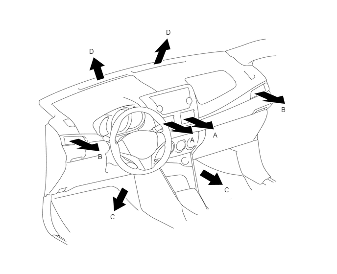
Air Outlets and Airflow Volume.
4.531,2.792 4.688,2.99
0.156,0.198
10
false
A
4.042,2.896 4.198,3.094
0.156,0.198
10
true
A
5.979,2.25 6.135,2.448
0.156,0.198
10
false
B
2.083,3.25 2.24,3.448
0.156,0.198
10
true
B
4.771,3.958 4.927,4.156
0.156,0.198
10
false
C
2.344,4.531 2.5,4.729
0.156,0.198
10
false
C
3.531,0.604 3.688,0.802
0.156,0.198
10
false
D
1.896,1.01 2.052,1.208
0.156,0.198
10
false
D
| Indication | Mode | FACE | FOOT | DEF | |
|---|---|---|---|---|---|
| CTR | SIDE | C | D | ||
| A | B | ||||
|
|
FACE | 
|
|

|

|
|
|
B/L | 
|
|

|
|
|
|
FOOT |
|

|
|
|
|
|
F/D |
|
|
|
|
|
|
DEF |
|
|
|
|
The size of each circle ○ indicates the ratio of airflow volume.