NETWORKING CAN COMMUNICATION SYSTEM TERMINALS OF ECU
- NOTICE:
- ·
After turning the ignition switch off, waiting time may be required before disconnecting the cable from the negative (-) battery terminal. Therefore, make sure to read the disconnecting the cable from the negative (-) battery terminal notices before proceeding with work.
Click hereGeneral>INTRODUCTION>REPAIR INSTRUCTION>PRECAUTION
·Turn the ignition switch off before inspecting CAN bus lines for a ground short.
·Before measuring the resistance of the CAN bus, turn the ignition switch off and leave the vehicle for 1 minute or more without operating the key, switches or opening or closing the doors. After that, disconnect the cable from the negative (-) battery terminal and leave the vehicle for 1 minute or more before measuring the resistance.
·This section describes the standard values for all CAN related components.
- HINT:
- ·
Operating the ignition switch, any other switches or a door triggers related ECU and sensor communication on the CAN. This communication will cause the resistance value to change.
·Even after DTCs are cleared, if a DTC is stored again after driving the vehicle for a while, the malfunction may be occurring due to vibration of the vehicle. In such a case, wiggling the ECUs or wire harness while performing the inspection below may help determine the cause of the malfunction.
NO. 1 CAN JUNCTION CONNECTOR (for LHD)
Check the No. 1 CAN junction connector.
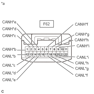
| *a | Front view of wire harness connector
(to No. 1 CAN Junction Connector) |
| *b | to DLC3 |
| *c | to Brake Actuator Assembly*1 |
| *d | to ECM |
| *e | to Airbag ECU Assembly*2 |
| *f | to Combination Meter Assembly |
| *g | to Certification ECU (Smart Key ECU Assembly)*3 |
| *h | to Air Conditioning Amplifier Assembly |
| *i | to Spiral Cable with Sensor Sub-assembly*4 |
Connection diagram
Check the connection diagram of the components which are connected to the No. 1 CAN junction connector.
| Terminal No. (Symbol) | Wiring Color | Connected to |
|---|---|---|
| F62-1 (CANH) | GR | DLC3 |
| F62-12 (CANL) | W | |
| F62-2 (CANH) | L | Brake actuator assembly*1 |
| F62-13 (CANL) | W | |
| F62-3 (CANH) | BE | ECM |
| F62-14 (CANL) | W | |
| F62-4 (CANH) | B | Airbag ECU assembly*2 |
| F62-15 (CANL) | W | |
| F62-6 (CANH) | G | Combination meter assembly |
| F62-17 (CANL) | W | |
| F62-7 (CANH) | L | Certification ECU (smart Key ECU assembly)*3 |
| F62-18 (CANL) | W | |
| F62-8 (CANH) | V | Air conditioning amplifier assembly |
| F62-19 (CANL) | W | |
| F62-9 (CANH) | R | Spiral cable with sensor sub-assembly*4 |
| F62-20 (CANL) | W |
*1: w/ ABS
*2: w/ Airbag System
*3: w/ Smart Entry and Start System
*4: w/ VSC
NO. 2 CAN JUNCTION CONNECTOR (for RHD)
Check the No. 2 CAN junction connector.
Connection diagram
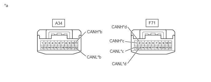
| *a | Front view of wire harness connector
(to No. 2 CAN Junction Connector) |
*b | to Brake Actuator Assembly |
| *c | to Combination Meter Assembly | *d | to No. 1 CAN Junction Connector |
Check the connection diagram of the components which are connected to the No. 2 CAN junction connector.
| Terminal No. (Symbol) | Wiring Color | Connected to |
|---|---|---|
| A34-11 (CANH) | L | Brake actuator assembly |
| A34-22 (CANL) | W | |
| F71-1 (CANH) | G | Combination meter assembly |
| F71-12 (CANL) | W | |
| F71-2 (CANH) | L | No. 1 CAN junction connector |
| F71-13 (CANL) | W |
NO. 1 CAN JUNCTION CONNECTOR (for RHD)
Check the No. 1 CAN junction connector.
Connection diagram
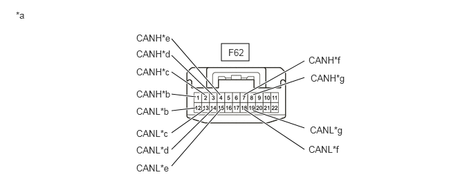
| *a | Front view of wire harness connector
(to No. 1 CAN Junction Connector) |
*b | to DLC3 |
| *c | to No. 2 CAN Junction Connector | *d | to ECM |
| *e | to Airbag ECU Assembly | *f | to Certification ECU (Smart Key ECU Assembly)*1 |
| *g | to Air Conditioning Amplifier Assembly | - | - |
Check the connection diagram of the components which are connected to the No. 1 CAN junction connector.
| Terminal No. (Symbol) | Wiring Color | Connected to |
|---|---|---|
| F62-1 (CANH) | GR | DLC3 |
| F62-12 (CANL) | W | |
| F62-2 (CANH) | L | No. 2 CAN junction connector |
| F62-13 (CANL) | W | |
| F62-3 (CANH) | BE | ECM |
| F62-14 (CANL) | W | |
| F62-4 (CANH) | B | Airbag ECU assembly |
| F62-15 (CANL) | W | |
| F62-7 (CANH) | L | Certification ECU (smart key ECU assembly)*1 |
| F62-18 (CANL) | W | |
| F62-8 (CANH) | V | Air Conditioning Amplifier Assembly |
| F62-19 (CANL) | W |
*1: w/ Smart Entry and Start System
DLC3
Disconnect the cable from the negative (-) battery terminal.
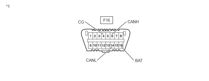
| *1 | DLC3 | - | - |
Measure the resistance according to the value(s) in the table below.
- Standard Resistance:
Terminal No. (Symbol) Wiring Color Terminal Description Condition Specified Condition F16-6 (CANH) - F16-14 (CANL) GR - W HIGH-level CAN bus line - LOW-level CAN bus line Cable disconnected from negative (-) battery terminal 54 to 69 Ω F16-6 (CANH) - F16-4 (CG) GR - W-B HIGH-level CAN bus line - Ground Cable disconnected from negative (-) battery terminal 200 Ω or higher F16-14 (CANL) - F16-4 (CG) W - W-B LOW-level CAN bus line - Ground Cable disconnected from negative (-) battery terminal 200 Ω or higher F16-6 (CANH) - F16-16 (BAT) GR - B HIGH-level CAN bus line - Battery positive (+) Cable disconnected from negative (-) battery terminal 6 kΩ or higher F16-14 (CANL) - F16-16 (BAT) W - B LOW-level CAN bus line - Battery positive (+) Cable disconnected from negative (-) battery terminal 6 kΩ or higher
ECM
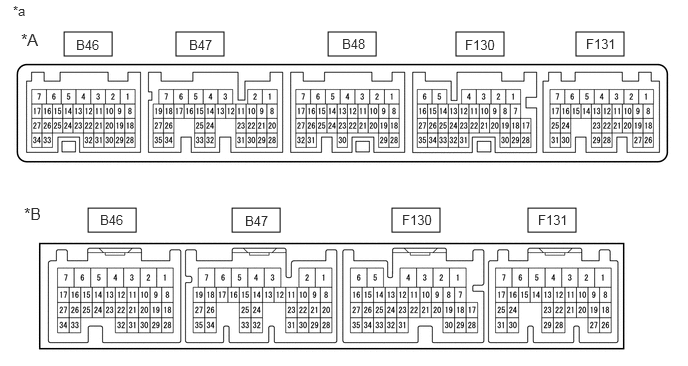
| *A | for CVT | *B | for Manual Transaxle |
| *a | Component without harness connected
(ECM) |
- | - |
Disconnect the cable from the negative (-) battery terminal.
Disconnect the ECM connectors.
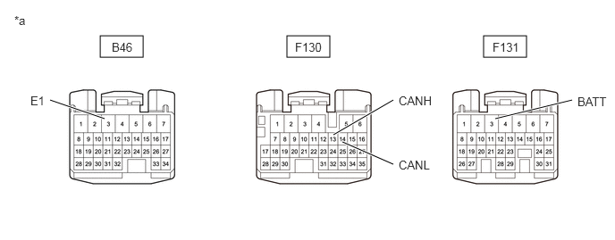
| *a | Front view of wire harness connector
(to ECM) |
- | - |
Measure the resistance according to the value(s) in the table below.
- Standard Resistance:
Terminal No. (Symbol) Wiring Color Terminal Description Condition Specified Condition F130-13 (CANH) - F130-14 (CANL) BE - W HIGH-level CAN bus line - LOW-level CAN bus line Cable disconnected from negative (-) battery terminal 108 to 132 Ω F130-13 (CANH) - B46-3 (E1) BE - W-B HIGH-level CAN bus line - Ground Cable disconnected from negative (-) battery terminal 200 Ω or higher F130-14 (CANL) - B46-3 (E1) W - W-B LOW-level CAN bus line - Ground Cable disconnected from negative (-) battery terminal 200 Ω or higher F130-13 (CANH) - F131-3 (BATT) BE - G HIGH-level CAN bus line - Battery positive (+) Cable disconnected from negative (-) battery terminal 6 kΩ or higher F130-14 (CANL) - F131-3 (BATT) W - G LOW-level CAN bus line - Battery positive (+) Cable disconnected from negative (-) battery terminal 6 kΩ or higher
BRAKE ACTUATOR ASSEMBLY (w/ VSC with CVT)
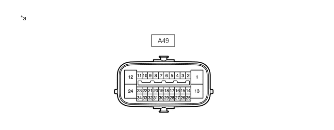
| *a | Component without harness connected
(Brake Actuator Assembly) |
- | - |
Disconnect the cable from the negative (-) battery terminal.
Disconnect the brake actuator assembly connector.
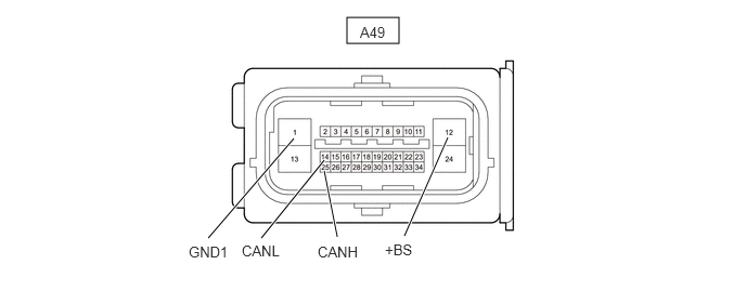
| *a | Front view of wire harness connector
(to Brake Actuator Assembly) |
- | - |
Measure the resistance according to the value(s) in the table below.
- Standard Resistance:
Terminal No. (Symbol) Wiring Color Terminal Description Condition Specified Condition A49-25 (CANH) - A49-14 (CANL) L - W HIGH-level CAN bus line - LOW-level CAN bus line Cable disconnected from negative (-) battery terminal 54 to 69 Ω A49-25 (CANH) - A49-1 (GND1) L - W-B HIGH-level CAN bus line - Ground Cable disconnected from negative (-) battery terminal 200 Ω or higher A49-14 (CANL) - A49-1 (GND1) W - W-B LOW-level CAN bus line - Ground Cable disconnected from negative (-) battery terminal 200 Ω or higher A49-25 (CANH) - A49-12 (+BS) L - W HIGH-level CAN bus line - Battery positive (+) Cable disconnected from negative (-) battery terminal 6 kΩ or higher A49-14 (CANL) - A49-12 (+BS) W - W LOW-level CAN bus line - Battery positive (+) Cable disconnected from negative (-) battery terminal 6 kΩ or higher
BRAKE ACTUATOR ASSEMBLY (w/ VSC except CVT)
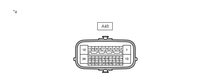
| *a | Component without harness connected
(Brake Actuator Assembly) |
- | - |
Disconnect the cable from the negative (-) battery terminal.
Disconnect the brake actuator assembly connector.
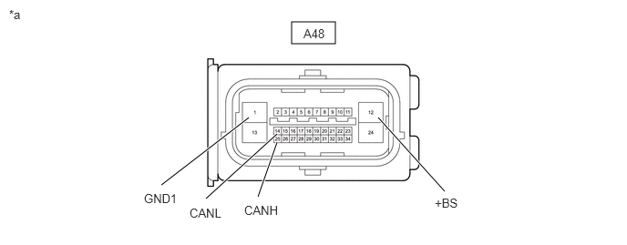
| *a | Front view of wire harness connector
(to Brake Actuator Assembly) |
- | - |
Measure the resistance according to the value(s) in the table below.
- Standard Resistance:
Terminal No. (Symbol) Wiring Color Terminal Description Condition Specified Condition A48-25 (CANH) - A48-14 (CANL) L - W HIGH-level CAN bus line - LOW-level CAN bus line Cable disconnected from negative (-) battery terminal 54 to 69 Ω A48-25 (CANH) - A48-1 (GND1) L - W-B HIGH-level CAN bus line - Ground Cable disconnected from negative (-) battery terminal 200 Ω or higher A48-14 (CANL) - A48-1 (GND1) W - W-B LOW-level CAN bus line - Ground Cable disconnected from negative (-) battery terminal 200 Ω or higher A48-25 (CANH) - A48-12 (+BS) L - W HIGH-level CAN bus line - Battery positive (+) Cable disconnected from negative (-) battery terminal 6 kΩ or higher A48-14 (CANL) - A48-12 (+BS) W - W LOW-level CAN bus line - Battery positive (+) Cable disconnected from negative (-) battery terminal 6 kΩ or higher
BRAKE ACTUATOR ASSEMBLY (w/ ABS without VSC for LHD and CVT)
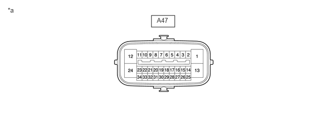
| *a | Component without harness connected
(Brake Actuator Assembly) |
- | - |
Disconnect the cable from the negative (-) battery terminal.
Disconnect the brake actuator assembly connector.
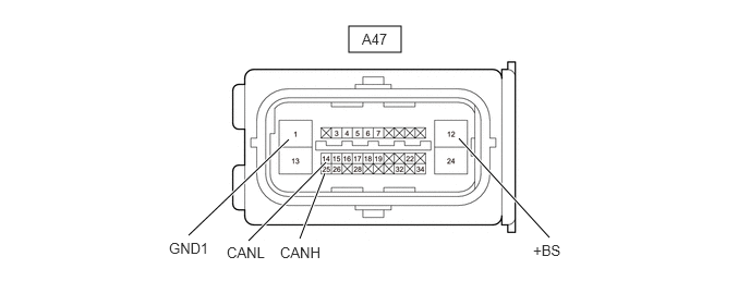
| *a | Front view of wire harness connector
(to Brake Actuator Assembly) |
- | - |
Measure the resistance according to the value(s) in the table below.
- Standard Resistance:
Terminal No. (Symbol) Wiring Color Terminal Description Condition Specified Condition A47-25 (CANH) - A47-14 (CANL) L - W HIGH-level CAN bus line - LOW-level CAN bus line Cable disconnected from negative (-) battery terminal 54 to 69 Ω A47-25 (CANH) - A47-1 (GND1) L - W-B HIGH-level CAN bus line - Ground Cable disconnected from negative (-) battery terminal 200 Ω or higher A47-14 (CANL) - A47-1 (GND1) W - W-B LOW-level CAN bus line - Ground Cable disconnected from negative (-) battery terminal 200 Ω or higher A47-25 (CANH) - A47-12 (+BS) L - W HIGH-level CAN bus line - Battery positive (+) Cable disconnected from negative (-) battery terminal 6 kΩ or higher A47-14 (CANL) - A47-12 (+BS) W - W LOW-level CAN bus line - Battery positive (+) Cable disconnected from negative (-) battery terminal 6 kΩ or higher
BRAKE ACTUATOR ASSEMBLY (w/ ABS without VSC except LHD and CVT)
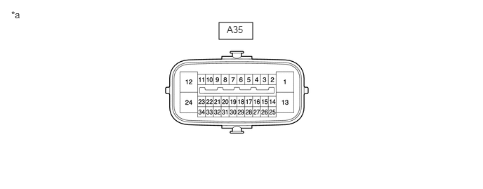
| *a | Component without harness connected
(Brake Actuator Assembly) |
- | - |
Disconnect the cable from the negative (-) battery terminal.
Disconnect the brake actuator assembly connector.
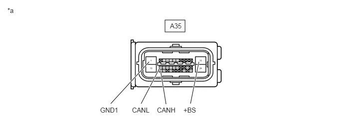
| *a | Front view of wire harness connector
(to Brake Actuator Assembly) |
- | - |
Measure the resistance according to the value(s) in the table below.
- Standard Resistance:
Terminal No. (Symbol) Wiring Color Terminal Description Condition Specified Condition A35-25 (CANH) - A35-14 (CANL) L - W HIGH-level CAN bus line - LOW-level CAN bus line Cable disconnected from negative (-) battery terminal 54 to 69 Ω A35-25 (CANH) - A35-1 (GND1) L - W-B HIGH-level CAN bus line - Ground Cable disconnected from negative (-) battery terminal 200 Ω or higher A35-14 (CANL) - A35-1 (GND1) W - W-B LOW-level CAN bus line - Ground Cable disconnected from negative (-) battery terminal 200 Ω or higher A35-25 (CANH) - A35-12 (+BS) L - W HIGH-level CAN bus line - Battery positive (+) Cable disconnected from negative (-) battery terminal 6 kΩ or higher A35-14 (CANL) - A35-12 (+BS) W - W LOW-level CAN bus line - Battery positive (+) Cable disconnected from negative (-) battery terminal 6 kΩ or higher
AIRBAG ECU ASSEMBLY (w/Airbag System with VSC)
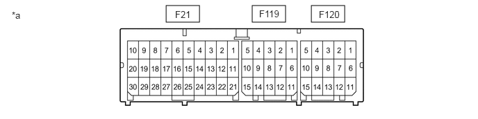
| *a | Component without harness connected
(Airbag ECU Assembly) |
- | - |
Disconnect the cable from the negative (-) battery terminal.
Disconnect the airbag ECU assembly connector.
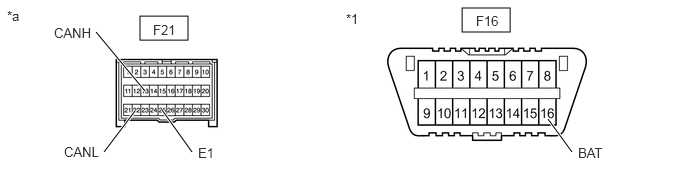
| *1 | DLC3 | - | - |
| *a | Front view of wire harness connector
(to Airbag ECU Assembly) |
- | - |
Measure the resistance according to the value(s) in the table below.
- Standard Resistance:
Terminal No. (Symbol) Wiring Color Terminal Description Condition Specified Condition F21-13 (CANH) - F21-22 (CANL) B - W HIGH-level CAN bus line - LOW-level CAN bus line Cable disconnected from negative (-) battery terminal 54 to 69 Ω F21-13 (CANH) - F21-25 (E1) B - W-B HIGH-level CAN bus line - Ground Cable disconnected from negative (-) battery terminal 200 Ω or higher F21-22 (CANL) - F21-25 (E1) W - W-B LOW-level CAN bus line - Ground Cable disconnected from negative (-) battery terminal 200 Ω or higher F21-13 (CANH) - F16-16 (BAT) B - B HIGH-level CAN bus line - Battery positive (+) Cable disconnected from negative (-) battery terminal 6 kΩ or higher F21-22 (CANL) - F16-16 (BAT) W - B LOW-level CAN bus line - Battery positive (+) Cable disconnected from negative (-) battery terminal 6 kΩ or higher
AIRBAG ECU ASSEMBLY (w/ Airbag System without VSC)
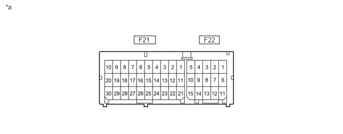
| *a | Component without harness connected
(Airbag ECU Assembly) |
- | - |
Disconnect the cable from the negative (-) battery terminal.
Disconnect the airbag ECU assembly connector.
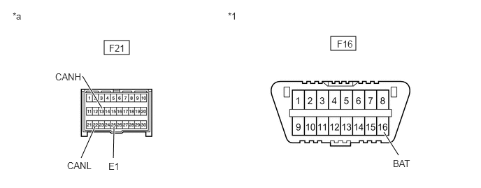
| *1 | DLC3 | - | - |
| *a | Front view of wire harness connector
(to Airbag ECU Assembly) |
- | - |
Measure the resistance according to the value(s) in the table below.
- Standard Resistance:
Terminal No. (Symbol) Wiring Color Terminal Description Condition Specified Condition F21-13 (CANH) - F21-22 (CANL) B - W HIGH-level CAN bus line - LOW-level CAN bus line Cable disconnected from negative (-) battery terminal 54 to 69 Ω F21-13 (CANH) - F21-25 (E1) B - W-B HIGH-level CAN bus line - Ground Cable disconnected from negative (-) battery terminal 200 Ω or higher F21-22 (CANL) - F21-25 (E1) W - W-B LOW-level CAN bus line - Ground Cable disconnected from negative (-) battery terminal 200 Ω or higher F21-13 (CANH) - F16-16 (BAT) B - B HIGH-level CAN bus line - Battery positive (+) Cable disconnected from negative (-) battery terminal 6 kΩ or higher F21-22 (CANL) - F16-16 (BAT) W - B LOW-level CAN bus line - Battery positive (+) Cable disconnected from negative (-) battery terminal 6 kΩ or higher
CERTIFICATION ECU (SMART KEY ECU ASSEMBLY) (w/ Smart Entry and Start System)
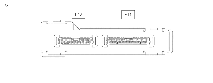
| *a | Component without harness connected
(Certification ECU (Smart Key ECU Assembly)) |
- | - |
Disconnect the cable from the negative (-) battery terminal.
Disconnect the certification ECU (smart key ECU assembly) connectors.
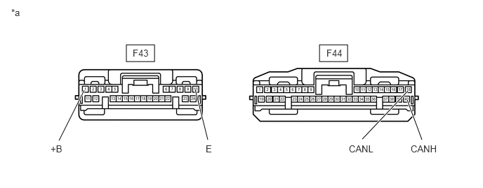
| *a | Front view of wire harness connector
(to Certification ECU (Smart Key ECU Assembly)) |
- | - |
Measure the resistance according to the value(s) in the table below.
- Standard Resistance:
Terminal No. (Symbol) Wiring Color Terminal Description Condition Specified Condition F44-40 (CANH) - F44-18 (CANL) L - W HIGH-level CAN bus line - LOW-level CAN bus line Cable disconnected from negative (-) battery terminal 54 to 69 Ω F44-40 (CANH) - F43-10 (E) L- W-B HIGH-level CAN bus line - Ground Cable disconnected from negative (-) battery terminal 200 Ω or higher F44-18 (CANL) - F43-10 (E) W - W-B LOW-level CAN bus line - Ground Cable disconnected from negative (-) battery terminal 200 Ω or higher F44-40 (CANH) - F43-1 (+B) L - V HIGH-level CAN bus line - Battery positive (+) Cable disconnected from negative (-) battery terminal 6 kΩ or higher F44-18 (CANL) - F43-1 (+B) W - V LOW-level CAN bus line - Battery positive (+) Cable disconnected from negative (-) battery terminal 6 kΩ or higher
COMBINATION METER ASSEMBLY
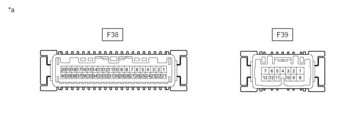
| *a | Component without harness connected
(Combination Meter Assembly) |
- | - |
Disconnect the cable from the negative (-) battery terminal.
Disconnect the combination meter assembly connector.
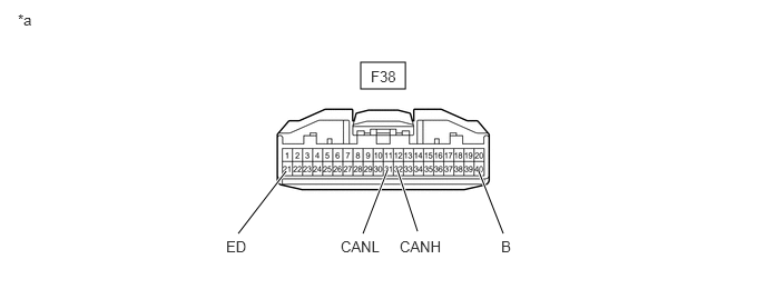
| *a | Front view of wire harness connector
(to Combination Meter Assembly) |
- | - |
Measure the resistance according to the value(s) in the table below.
- Standard Resistance:
Terminal No. (Symbol) Wiring Color Terminal Description Condition Specified Condition F38-32 (CANH) - F38-31 (CANL) G - W HIGH-level CAN bus line - LOW-level CAN bus line Cable disconnected from negative (-) battery terminal 108 to 132 Ω F38-32 (CANH) - F38-21 (ED) G - W-B HIGH-level CAN bus line - Ground Cable disconnected from negative (-) battery terminal 200 Ω or higher F38-31 (CANL) - F38-21 (ED) W - W-B LOW-level CAN bus line - Ground Cable disconnected from negative (-) battery terminal 200 Ω or higher F38-32 (CANH) - F38-40 (B) G - B HIGH-level CAN bus line - Battery positive (+) Cable disconnected from negative (-) battery terminal 6 kΩ or higher F38-31 (CANL) - F38-40 (B) W - B LOW-level CAN bus line - Battery positive (+) Cable disconnected from negative (-) battery terminal 6 kΩ or higher
AIR CONDITIONING AMPLIFIER ASSEMBLY (for Automatic Air Conditioning System)
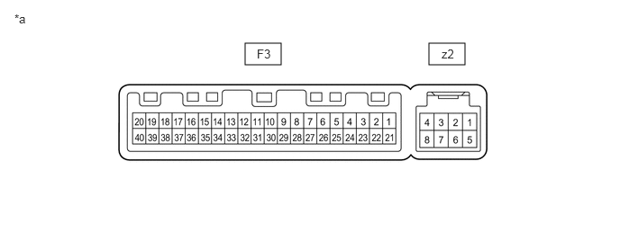
| *a | Component without harness connected
(Air Conditioning Amplifier Assembly) |
- | - |
Disconnect the cable from the negative (-) battery terminal.
Disconnect the air conditioning amplifier assembly connector.
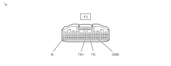
| *a | Front view of wire harness connector
(to Air Conditioning Amplifier Assembly) |
- | - |
Measure the resistance according to the value(s) in the table below.
- Standard Resistance:
Terminal No. (Symbol) Wiring Color Terminal Description Condition Specified Condition F3-11 (TX+) - F3-12 (TX-) V - W HIGH-level CAN bus line - LOW-level CAN bus line Cable disconnected from negative (-) battery terminal 54 to 69 Ω F3-11 (TX+) - F3-14 (GND) V - W-B HIGH-level CAN bus line - Ground Cable disconnected from negative (-) battery terminal 200 Ω or higher F3-12 (TX-) - F3-14 (GND) W - W-B LOW-level CAN bus line - Ground Cable disconnected from negative (-) battery terminal 200 Ω or higher F3-11 (TX+) - F3-21 (B) V - GR HIGH-level CAN bus line - Battery positive (+) Cable disconnected from negative (-) battery terminal 6 kΩ or higher F3-12 (TX-) - F3-21 (B) W - GR LOW-level CAN bus line - Battery positive (+) Cable disconnected from negative (-) battery terminal 6 kΩ or higher
AIR CONDITIONING AMPLIFIER ASSEMBLY (for Manual Air Conditioning System)
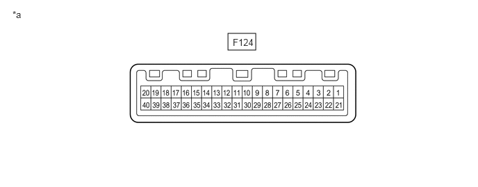
| *a | Component without harness connected
(Air Conditioning Amplifier Assembly) |
- | - |
Disconnect the cable from the negative (-) battery terminal.
Disconnect the air conditioning amplifier connector.
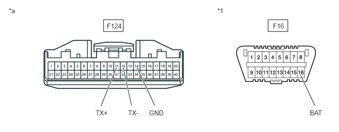
| *1 | DLC3 | - | - |
| *a | Front view of wire harness connector
(to Air Conditioning Amplifier Assembly) |
- | - |
Measure the resistance according to the value(s) in the table below.
- Standard Resistance:
Terminal No. (Symbol) Wiring Color Terminal Description Condition Specified Condition F124-11 (TX+) - F124-12 (TX-) V - W HIGH-level CAN bus line - LOW-level CAN bus line Cable disconnected from negative (-) battery terminal 54 to 69 Ω F124-11 (TX+) - F124-14 (GND) V - W-B HIGH-level CAN bus line - Ground Cable disconnected from negative (-) battery terminal 200 Ω or higher F124-12 (TX-) - F124-14 (GND) W - W-B LOW-level CAN bus line - Ground Cable disconnected from negative (-) battery terminal 200 Ω or higher F124-11 (TX+) - F16-16 (BAT) V - B HIGH-level CAN bus line - Battery positive (+) Cable disconnected from negative (-) battery terminal 6 kΩ or higher F124-12 (TX-) - F16-16 (BAT) W - B LOW-level CAN bus line - Battery positive (+) Cable disconnected from negative (-) battery terminal 6 kΩ or higher
SPIRAL CABLE WITH SENSOR SUB-ASSEMBLY (w/ VSC)
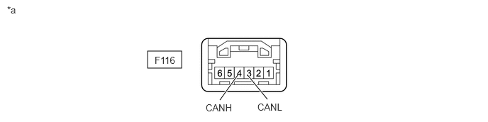
| *a | Component without harness connected
(Spiral Cable with Sensor Sub-assembly) |
- | - |
Disconnect the cable from the negative (-) battery terminal.
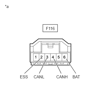
| *a | Front view of wire harness connector
(to Spiral Cable with Sensor Sub-assembly) |
Disconnect the spiral cable with sensor sub-assembly connector.
Measure the resistance according to the value(s) in the table below.
- Standard Resistance:
Terminal No. (Symbol) Wiring Color Terminal Description Condition Specified Condition F116-4 (CANH) - F116-3 (CANL) R - W HIGH-level CAN bus line - LOW-level CAN bus line Cable disconnected from negative (-) battery terminal 54 to 69 Ω F116-4 (CANH) - F116-2 (ESS) R- W-B HIGH-level CAN bus line - Ground Cable disconnected from negative (-) battery terminal 200 Ω or higher F116-3 (CANL) - F116-2 (ESS) W - W-B LOW-level CAN bus line - Ground Cable disconnected from negative (-) battery terminal 200 Ω or higher F116-4 (CANH) - F116-6 (BAT) R - B HIGH-level CAN bus line - Battery positive (+) Cable disconnected from negative (-) battery terminal 6 kΩ or higher F116-3 (CANL) - F116-6 (BAT) W - B LOW-level CAN bus line - Battery positive (+) Cable disconnected from negative (-) battery terminal 6 kΩ or higher