RM30M0E
_52
Drivetrain
_052750
K411 CVT
_0254682
CONTINUOUSLY VARIABLE TRANSAXLE SYSTEM
U
K411 CVT CONTINUOUSLY VARIABLE TRANSAXLE SYSTEM TERMINALS OF ECM
ECM
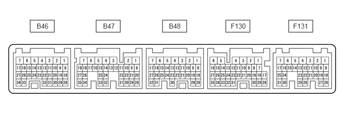
0.625,0.417 1.125,0.667
0.5,0.25
1.99,0.417 2.49,0.667
0.5,0.25
3.365,0.417 3.865,0.667
0.5,0.25
4.677,0.417 5.177,0.667
0.5,0.25
5.979,0.417 6.479,0.667
0.5,0.25
0.76,0.458 1.219,0.656
0.458,0.198
10
false
B46
2.135,0.458 2.594,0.656
0.458,0.198
10
false
B47
3.5,0.458 3.958,0.656
0.458,0.198
10
false
B48
4.781,0.458 5.24,0.656
0.458,0.198
10
false
F130
6.073,0.458 6.531,0.656
0.458,0.198
10
false
F131
- HINT:
-
The standard voltage and resistance of each ECM terminal is shown in the table below.
-
In the table, first follow the information under "Condition". Look under "Terminal No. (Symbol)" for the terminals to be inspected. The standard voltage or resistance between the terminals is shown under "Specified Condition".
-
Use the illustration above as a reference for the ECM terminals.
| Terminals No. (Symbol) | Wiring Color | Terminal Description | Condition | Specified Condition |
|---|---|---|---|---|
| F131-3 (BATT) - B46-3 (E1) | G - W-B | Battery (for measuring battery voltage and for ECM memory) | Always | 11 to 14 V |
| F131-1 (+B) - B46-3 (E1) | R - W-B | Power source of ECM | Ignition switch ON | 11 to 14 V |
| F131-2 (+B2) - B46-3 (E1) | R - W-B | Power source of ECM | Ignition switch ON | 11 to 14 V |
| F130-13 (CANH) - B46-3 (E1) | BE - W-B | CAN communication line | Ignition switch ON | Pulse generation |
| B47-15 (NSW) - B46-3 (E1) | W - W-B | Park/neutral position switch signal | Ignition switch ON and shift lever in P or N | Below 1 V |
| Ignition switch ON and shift lever not in P or N | 11 to 14 V | |||
| F130-14 (CANL) - B46-3 (E1) | W - W-B | CAN communication line | Ignition switch ON | Pulse generation |
| F130-6 (MREL) - B46-3 (E1) | L - W-B | EFI relay | Ignition switch ON | 11 to 14 V |
| B48-30 (S) - B46-3 (E1) | V - W-B | M position switch signal | Ignition switch ON and shift lever in M | 11 to 14 V |
| Ignition switch ON and shift lever in any position except M | Below 1 V | |||
| B48-17 (SFTU) - B46-3 (E1) | R - W-B | Up shift position switch signal | Ignition switch ON and shift lever in M | 11 to 14 V |
| Ignition switch ON and shift lever held in "+" (Up shift) | Below 1 V | |||
| B48-27 (SFTD) - B46-3 (E1) | L - W-B | Down shift position switch signal | Ignition switch ON and shift lever in M | 11 to 14 V |
| Ignition switch ON and shift lever held in "-" (Down shift) | Below 1 V | |||
| B46-5 (+BM) - B46-3 (E1) | R - W-B | Power source of ECM | Always | 11 to 14 V |
| B48-7 (SLT+) - B48-6 (SLT-) | P - L | Shift solenoid valve SLT signal | Engine idling | Pulse generation |
| B48-11 (DS1) - B46-3 (E1) | W - W-B | Shift solenoid valve DS1 signal | Accelerator pedal released while driving with shift lever in D | Pulse generation |
| B48-10 (DS2) - B46-3 (E1) | R - W-B | Shift solenoid valve DS2 signal | Accelerator pedal depressed further after driving at constant vehicle speed with shift lever in D | Pulse generation |
| B48-2 (SLU+) - B48-1 (SLU-) | SB - GR | Shift solenoid valve SLU signal | Lock-up turned from OFF to ON | Pulse generation |
| B48-5 (SLS+) - B48-4 (SLS-) | V - BE | Shift solenoid valve SLS signal | Engine idling | Pulse generation |
| B46-3 (E1) - Body ground | W-B - Body ground | Ground | Always | Below 1 Ω |
| F130-8 (R) - B46-3 (E1) | GR - W-B | R position switch signal | Ignition switch ON and shift lever in R | 11 to 14 V |
| Ignition switch ON and shift lever not in R | Below 1 V | |||
| F130-18 (D) - B46-3 (E1) | L - W-B | D position switch signal | Ignition switch ON and shift lever in D | 11 to 14 V |
| Ignition switch ON and shift lever not in D | Below 1 V | |||
| B48-24 (N) - B46-3 (E1) | B - W-B | N position switch signal | Ignition switch ON and shift lever in N | 11 to 14 V |
| Ignition switch ON and shift lever not in N | Below 1 V | |||
| B48-25 (P) - B46-3 (E1) | P - W-B | P position switch signal | Ignition switch ON and shift lever in P | 11 to 14 V |
| Ignition switch ON and shift lever not in P | Below 1 V | |||
| F130-24 (PTO) - F130-31 (EPTO) | L - BE | Oil pressure sensor signal | Engine idling with shift lever in P | 0.8 to 1.2 V |
| F130-32 (VCPT) - F130-31 (EPTO) | V - BE | Power supply for oil pressure sensor | Ignition switch ON | 4.75 to 5.25 V |
| B48-32 (NIN+) - B48-31 (NIN-) | Y - LG | Transmission revolution sensor (NIN) signal | When driving with shift lever in D | Pulse generation |
| B48-19 (NTO) - B46-3 (E1) | G - W-B | Transmission revolution sensor (NT) signal | When driving with shift lever in D | Pulse generation |
| B48-29 (NTB) - B46-3 (E1) | BE - W-B | Power supply for transmission revolution sensor (NT) | Ignition switch ON | 11 to 14 V |
| B47-9 (NOTO) - B46-3 (E1) | L - W-B | Transmission revolution sensor (NOUT) signal | When driving with shift lever in D | Pulse generation |
| B47-10 (NOTB) - B46-3 (E1) | G - W-B | Power supply for transmission revolution sensor (NOUT) | Ignition switch ON | 11 to 14 V |
| B48-20 (THO1) - B48-21 (ETHO) | Y - B | CVT fluid temperature sensor signal | CVT fluid temperature: 60 to 120°C (140 to 248°F) | 0.2 to 1.0 V |
| Terminals No. (Symbol) | Wiring Color | Terminal Description | Condition | Specified Condition |
|---|---|---|---|---|
| F131-3 (BATT) - B46-3 (E1) | G - W-B | Battery (for measuring battery voltage and for ECM memory) | Always | 11 to 14 V |
| F131-1 (+B) - B46-3 (E1) | R - W-B | Power source of ECM | Ignition switch ON | 11 to 14 V |
| F131-2 (+B2) - B46-3 (E1) | R - W-B | Power source of ECM | Ignition switch ON | 11 to 14 V |
| F130-13 (CANH) - B46-3 (E1) | BE - W-B | CAN communication line | Ignition switch ON | Pulse generation |
| B47-15 (NSW) - B46-3 (E1) | W - W-B | Park/neutral position switch signal | Ignition switch ON and shift lever in P or N | Below 1 V |
| Ignition switch ON and shift lever not in P or N | 11 to 14 V | |||
| F130-14 (CANL) - B46-3 (E1) | W - W-B | CAN communication line | Ignition switch ON | Pulse generation |
| F130-6 (MREL) - B46-3 (E1) | L - W-B | EFI relay | Ignition switch ON | 11 to 14 V |
| B48-30 (S) - B46-3 (E1) | V - W-B | M position switch signal | Ignition switch ON and shift lever in M | 11 to 14 V |
| Ignition switch ON and shift lever in any position except M | Below 1 V | |||
| B48-17 (SFTU) - B46-3 (E1) | R - W-B | Up shift position switch signal | Ignition switch ON and shift lever in M | 11 to 14 V |
| Ignition switch ON and shift lever held in "+" (Up shift) | Below 1 V | |||
| B48-27 (SFTD) - B46-3 (E1) | L - W-B | Down shift position switch signal | Ignition switch ON and shift lever in M | 11 to 14 V |
| Ignition switch ON and shift lever held in "-" (Down shift) | Below 1 V | |||
| B46-5 (+BM) - B46-3 (E1) | R - W-B | Power source of ECM | Always | 11 to 14 V |
| B48-7 (SLT+) - B48-6 (SLT-) | P - L | Shift solenoid valve SLT signal | Engine idling | Pulse generation |
| B48-11 (DS1) - B46-3 (E1) | W - W-B | Shift solenoid valve DS1 signal | Accelerator pedal released while driving with shift lever in D | Pulse generation |
| B48-10 (DS2) - B46-3 (E1) | R - W-B | Shift solenoid valve DS2 signal | Accelerator pedal depressed further after driving at constant vehicle speed with shift lever in D | Pulse generation |
| B48-2 (SLU+) - B48-1 (SLU-) | SB - GR | Shift solenoid valve SLU signal | Lock-up turned from OFF to ON | Pulse generation |
| B48-5 (SLS+) - B48-4 (SLS-) | V - BE | Shift solenoid valve SLS signal | Engine idling | Pulse generation |
| B46-3 (E1) - Body ground | W-B - Body ground | Ground | Always | Below 1 Ω |
| F130-8 (R) - B46-3 (E1) | GR - W-B | R position switch signal | Ignition switch ON and shift lever in R | 11 to 14 V |
| Ignition switch ON and shift lever not in R | Below 1 V | |||
| F130-18 (D) - B46-3 (E1) | L - W-B | D position switch signal | Ignition switch ON and shift lever in D | 11 to 14 V |
| Ignition switch ON and shift lever not in D | Below 1 V | |||
| B48-24 (N) - B46-3 (E1) | V - W-B | N position switch signal | Ignition switch ON and shift lever in N | 11 to 14 V |
| Ignition switch ON and shift lever not in N | Below 1 V | |||
| B48-25 (P) - B46-3 (E1) | P - W-B | P position switch signal | Ignition switch ON and shift lever in P | 11 to 14 V |
| Ignition switch ON and shift lever not in P | Below 1 V | |||
| F130-24 (PTO) - F130-31 (EPTO) | L - BE | Oil pressure sensor signal | Engine idling with shift lever in P | 0.8 to 1.2 V |
| F130-32 (VCPT) - F130-31 (EPTO) | V - BE | Power supply for oil pressure sensor | Ignition switch ON | 4.75 to 5.25 V |
| B48-32 (NIN+) - B48-31 (NIN-) | Y - LG | Transmission revolution sensor (NIN) signal | When driving with shift lever in D | Pulse generation |
| B48-19 (NTO) - B46-3 (E1) | G - W-B | Transmission revolution sensor (NT) signal | When driving with shift lever in D | Pulse generation |
| B48-29 (NTB) - B46-3 (E1) | BE - W-B | Power supply for transmission revolution sensor (NT) | Ignition switch ON | 11 to 14 V |
| B47-9 (NOTO) - B46-3 (E1) | L - W-B | Transmission revolution sensor (NOUT) signal | When driving with shift lever in D | Pulse generation |
| B47-10 (NOTB) - B46-3 (E1) | G - W-B | Power supply for transmission revolution sensor (NOUT) | Ignition switch ON | 11 to 14 V |
| B48-20 (THO1) - B48-21 (ETHO) | Y - B | CVT fluid temperature sensor signal | CVT fluid temperature: 60 to 120°C (140 to 248°F) | 0.2 to 1.0 V |