POWER ASSIST SYSTEMS POWER STEERING SYSTEM(for TMMIN Made) TERMINALS OF ECU
CHECK POWER STEERING ECU ASSEMBLY
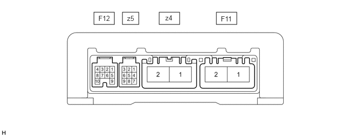
Measure the voltage, resistance and check for pulses according to the value(s) in the table below.
- NOTICE:
- ·
Check if the power steering ECU assembly connectors are securely connected by pulling on them from the backside.
·If the power steering warning light is illuminated due to a malfunction, the fail-safe function may cause the voltage of the power steering ECU assembly terminals to become 0 V.
| Terminal No. (Symbol) | Wiring Color | Terminal Description | Condition | Specified Condition |
|---|---|---|---|---|
| F11-1 (PIG) - F11-2 (PGND) | B - W-B | Power source | Always | 11 to 14 V |
| F11-2 (PGND) - Body ground | W-B - Body ground | Body ground | Always | Below 1 Ω |
| F12-1 (IG) - F11-2 (PGND) | L - W-B | IG power source | Ignition switch ON | 11 to 14 V |
| F12-2 (SPD) - F11-2 (PGND) | P - W-B | Vehicle speed signal | Vehicle being driven | Pulse generation (see waveform 1) |
| F12-3 (TC) - F11-2 (PGND) | L - W-B | TC terminal | Ignition switch ON | 11 to 14 V |
| F12-4 (SIL) - F11-2 (PGND) | B - W-B | GTS communication line | ·
Ignition switch ON ·
Communication not performed with GTS |
11 to 14 V |
| F12-5 (TACH) - F11-2 (PGND) | W - W-B | Engine speed signal | Engine running | Pulse generation (see waveform 2) |
| F12-6 (TS) - F11-2 (PGND) | GR - W-B | TS terminal | Ignition switch ON | 11 to 14 V |
| F12-9 (IDUP) - F11-2 (PGND) | B - W-B | ECM | Ignition switch ON | 5 to 14 V |
| F12-10 (WL) - F11-2 (PGND) | R - W-B | Power steering warning light output signal | ·
Engine running ·
Power steering warning light off |
Below 0.2 V |
·
Ignition switch ON ·
Power steering warning light on |
5.5 to 7 V | |||
| z4-1 (M1) - F11-2 (PGND) | R - W-B | Power steering motor assembly | ·
Ignition switch ON ·
Steering wheel turned to left |
6 to 11 V |
·
Ignition switch ON ·
Steering wheel turned to right |
11 to 14 V | |||
| z4-2 (M2) - F11-2 (PGND) | B - W-B | Power steering motor assembly | ·
Ignition switch ON ·
Steering wheel turned to left |
11 to 14 V |
·
Ignition switch ON ·
Steering wheel turned to right |
6 to 11 V | |||
| z5-1 (TRQ2) - z5-2 (TRQG) | Y - B | Torque sensor | Engine running, steering wheel not turned (without load) | 2.3 to 2.7 V |
| Engine running, steering wheel turned to right with vehicle stopped | 1.2 to 2.5 V | |||
| Engine running, steering wheel turned to left with vehicle stopped | 2.5 to 3.8 V | |||
| z5-2 (TRQG) - F11-2 (PGND) | B - W-B | Torque sensor | Always | Below 1 Ω |
| z5-8 (TRQV) - z5-2 (TRQG) | R - B | Torque sensor | Ignition switch ON | 4.5 to 5.5 V |
| z5-9 (TRQ1) - z5-2 (TRQG) | W - B | Torque sensor | Engine running, steering wheel not turned (without load) | 2.3 to 2.7 V |
| Engine running, steering wheel turned to right with vehicle stopped | 2.5 to 3.8 V | |||
| Engine running, steering wheel turned to left with vehicle stopped | 1.2 to 2.5 V |
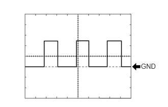
Using an oscilloscope, check waveform 1.
| Item | Contents |
|---|---|
| Terminal No. (Symbol) | F12-2 (SPD) - F11-2 (PGND) |
| Tool Setting | 5 V/DIV., 20 ms./DIV. |
| Vehicle Condition | Vehicle being driven at approximately 20 km/h (12 mph) |
- HINT:
-
The wavelength becomes shorter as the vehicle speed increases.
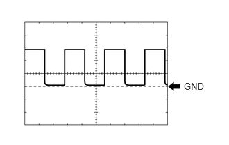
Using an oscilloscope, check waveform 2.
| Item | Contents |
|---|---|
| Terminal No. (Symbol) | F12-5 (TACH) - F11-2 (PGND) |
| Tool Setting | 5 V/DIV., 10 ms./DIV. |
| Vehicle Condition | Idling |
- HINT:
-
The wavelength becomes shorter as the engine speed increases.