REAR SUSPENSION REAR AXLE BEAM(for Rear Drum Brake) REMOVAL
PROCEDURE

 1.REMOVE REAR WHEELS
2.DRAIN BRAKE FLUID
89516D
3.SEPARATE SKID CONTROL SENSOR WIRE LH
89516C
4.SEPARATE SKID CONTROL SENSOR WIRE RH
- HINT:
-
Use the same procedure described for the LH side.
47319F
5.SEPARATE REAR FLEXIBLE HOSE LH
47318F
6.SEPARATE REAR FLEXIBLE HOSE RH
- HINT:
-
Use the same procedure described for the LH side.
46430
7.SEPARATE NO. 3 PARKING BRAKE CABLE ASSEMBLY
46420
8.SEPARATE NO. 2 PARKING BRAKE CABLE ASSEMBLY
- HINT:
-
Use the same procedure described for the No. 3 parking brake cable assembly.
58251D
9.REMOVE FRONT FLOOR PANEL BRACE LH
58251D
10.REMOVE FRONT FLOOR PANEL BRACE RH
- HINT:
-
Use the same procedure described for the LH side.
42403
11.REMOVE REAR BRAKE DRUM SUB-ASSEMBLY
58910C
12.REMOVE REAR CONSOLE BOX ASSEMBLY
42450B
13.REMOVE REAR AXLE HUB AND BEARING ASSEMBLY LH
42450A
14.REMOVE REAR AXLE HUB AND BEARING ASSEMBLY RH
- HINT:
-
Use the same procedure described for the LH side.
42110F
15.LOOSEN REAR AXLE BEAM ASSEMBLY
48231B
16.REMOVE REAR COIL SPRING LH
48231A
17.REMOVE REAR COIL SPRING RH
- HINT:
-
Use the same procedure described for the LH side.
42110F
18.REMOVE REAR AXLE BEAM ASSEMBLY
Support the rear axle beam assembly with an engine lifter using the 4 plate lift attachments or equivalent tools as shown in the illustration.
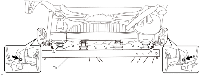
| *a | Plate Lift Attachment | *b | Engine Lifter |
- NOTICE:
-
Make sure to secure the rear axle beam assembly to prevent it from dropping.
Remove the 2 bolts A and separate the rear axle beam assembly from the rear shock absorber assemblies LH and RH.
Remove the 2 bolts B and rear axle beam assembly from the body.
48725G
19.REMOVE REAR AXLE CARRIER BUSH LH
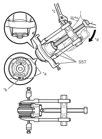
| *a | Bush Rib |
| *b | Alignment Mark |
| *c | Hold |
| *d | Turn |
Place a matchmark on the rear axle beam assembly with it aligned with the alignment mark of the rear axle carrier bush LH.
Using a chisel and hammer, bend the 2 portions of the bush rib.
- NOTICE:
- ·
Bend the bush rib until the claw of SST can be suspended.
·When removing the bush, do not rub off the matchmark on the rear axle beam assembly.
Using SST, remove the rear axle carrier bush LH from the rear axle beam assembly.
- SST
- 09710-26011 (09710-05061)
09950-40011 (09951-04020, 09952-04010, 09953-04030, 09954-04020, 09955-04051, 09957-04010, 09958-04011)
09950-60010 (09951-00530)
- NOTICE:
-
Apply grease to the threads and tip of the SST center bolt before use.
48725F
20.REMOVE REAR AXLE CARRIER BUSH RH
- HINT:
-
Use the same procedure described for the LH side.