Home › Audio / Visual / Telematics › AUDIO / VIDEO › STEERING PAD SWITCH › from 2018.01
RM30M0E _56 Audio / Visual / Telematics _017106 AUDIO / VIDEO _0089074 STEERING PAD SWITCH G

AUDIO / VIDEO  STEERING PAD SWITCH  INSPECTION  


PROCEDURE

Hide 84250A 1.INSPECT STEERING PAD SWITCH ASSEMBLY (Type A)

a.

Measure the resistance according to the value(s) in the table below.
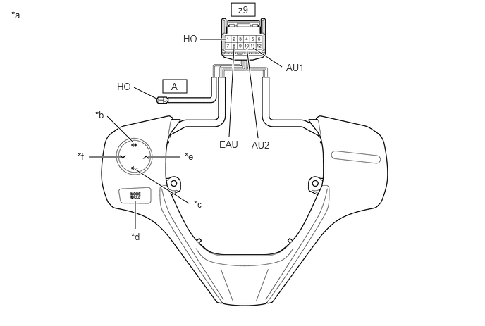
E362843C01
3.417,0.042 3.771,0.24 0.354,0.198 2.406,1.177 2.76,1.375 0.354,0.198 2.958,0.583 3.333,0.583 true 3.74,0.708 4.167,0.99 true 3.458,0.698 3.385,2.021 true 3.646,0.708 3.813,2.042 true 1.979,1.292 2.313,1.458 false 1.583,1.719 1.969,2.104 true 1.313,2.323 1.781,2.323 true 2.188,2.323 2.656,2.323 true 1.99,2.5 2.792,3.01 true 2,3.385 2,2.979 true 0.167,0.135 0.427,0.375 0.26,0.24 10 false *a 1.406,1.615 1.646,1.802 0.24,0.188 10 false *b 2.865,2.938 3.104,3.135 0.24,0.198 10 false *c 1.938,3.417 2.219,3.625 0.281,0.208 10 false *d 2.729,2.229 2.99,2.438 0.26,0.208 10 false *e 1.146,2.229 1.385,2.427 0.24,0.198 10 false *f 3.521,0.063 3.771,0.25 0.25,0.188 10 false z9 2.708,0.49 3.01,0.677 0.302,0.188 10 false HO 4.229,0.917 4.615,1.104 0.385,0.188 10 false AU1 3.24,2.052 3.625,2.24 0.385,0.188 10 false EAU 3.719,2.063 4.104,2.25 0.385,0.188 10 false AU2 2.531,1.198 2.688,1.375 0.156,0.177 10 false A 1.729,1.198 2.031,1.385 0.302,0.188 10 false HO
*a Component without harness connected
(Steering Pad Switch Assembly)
*b Volume+
*c Volume- *d MODE
*e Seek+ *f Seek-


Standard Resistance:
Tester Connection Condition Specified Condition
z9-1 (HO) - A-1 (HO) Always Below 2.5 Ω
z9-11 (AU1) - z9-8 (EAU) No switch pushed 95 to 105 kΩ
Seek+ switch pushed Below 2.5 Ω
Seek- switch pushed 313 to 345 Ω
Volume+ switch pushed 950 to 1050 Ω
Volume- switch pushed 2955 to 3265 Ω
z9-10 (AU2) - z9-8 (EAU) No switch pushed 95 to 105 kΩ
MODE switch pushed Below 2.5 Ω


HINT:

If the result is not as specified, replace the steering pad switch assembly.


b.

Check the illumination.

E362844C02
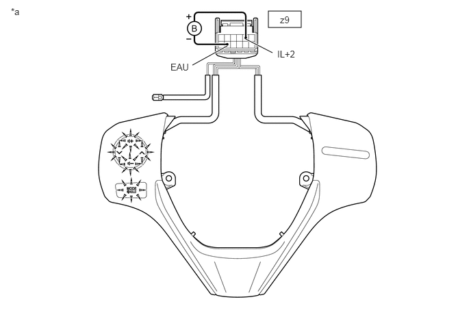
4.083,0.167 4.583,0.417 0.5,0.25 2.927,0.99 3.458,0.698 true 4.146,0.802 3.74,0.594 true 0.167,0.094 0.438,0.302 0.271,0.208 10 false *a 2.594,0.938 2.948,1.115 0.354,0.177 10 false EAU 4.219,0.74 4.573,0.917 0.354,0.177 10 false IL+2 4.26,0.219 4.615,0.396 0.354,0.177 10 false z9
*a Component without harness connected
(Steering Pad Switch Assembly)
- -


i.

Connect a positive (+) lead from the battery to terminal z9-5 (IL+2) and a negative (-) lead to terminal z9-8 (EAU) of the steering pad switch assembly connector.


ii.

Check that the steering pad switch assembly illumination illuminates.

OK:

The steering pad switch assembly illumination illuminates.


HINT:

If the result is not as specified, replace the steering pad switch assembly.


Hide 84250A 2.INSPECT STEERING PAD SWITCH ASSEMBLY (Type B)

a.

Measure the resistance according to the value(s) in the table below.
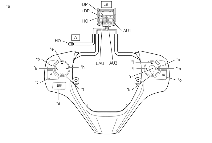
E362839C01
3.427,0.042 3.771,0.26 0.344,0.219 2.417,1.167 2.698,1.365 0.281,0.198 3.063,0.396 3.438,0.563 true 3.01,0.146 3.542,0.542 true 3.01,0.708 3.344,0.583 true 3.76,0.698 4.115,1.021 true 3.635,0.698 3.813,2.021 true 3.469,0.688 3.375,2.021 true 2.094,1.375 2.313,1.458 false 1.854,1.688 2.094,2.104 true 1.396,1.99 1.677,2.177 true 1.323,2.313 1.875,2.313 true 1.365,2.781 1.688,2.635 true 1.99,2.99 1.99,3.365 true 2.146,2.5 2.688,3.01 true 2.302,2.271 2.656,2.271 true 4.583,2.115 5.146,2.115 true 4.615,2.313 4.917,2.313 true 4.479,2.573 5.125,2.323 true 4.458,3.031 5.156,2.51 true 5.573,2.177 5.896,2.031 true 5.333,2.313 5.885,2.313 true 5.583,2.594 5.927,2.688 true 0.208,0.125 0.479,0.354 0.271,0.229 10 false *a 1.219,1.906 1.531,2.063 0.313,0.156 10 false *b 1.188,2.688 1.479,2.885 0.292,0.198 10 false *c 1.906,3.406 2.219,3.563 0.313,0.156 10 false *d 1.688,1.573 1.958,1.75 0.271,0.177 10 false *e 2.75,2.938 2.969,3.146 0.219,0.208 10 false *f 1.135,2.188 1.385,2.406 0.25,0.219 10 false *g 2.729,2.177 2.99,2.385 0.26,0.208 10 false *h 4.344,2.49 4.542,2.677 0.198,0.188 10 false *i 4.438,2 4.74,2.208 0.302,0.208 10 false *j 4.281,2.927 4.594,3.083 0.313,0.156 10 false *k 4.458,2.24 4.771,2.396 0.313,0.156 10 false *l 5.948,2.229 6.208,2.427 0.26,0.198 10 false *m 5.958,1.917 6.271,2.115 0.313,0.198 10 false *n 6.01,2.615 6.26,2.854 0.25,0.24 10 false *o 3.51,0.063 3.729,0.24 0.219,0.177 10 false z9 2.76,0.281 3.104,0.458 0.344,0.177 10 false +DP 2.781,0.625 3.031,0.802 0.25,0.177 10 false HO 2.729,0.063 3.073,0.24 0.344,0.177 10 false -DP 4.167,0.948 4.51,1.135 0.344,0.188 10 false AU1 3.698,2.042 4.042,2.229 0.344,0.188 10 false AU2 3.24,2.052 3.583,2.24 0.344,0.188 10 false EAU 2.51,1.177 2.76,1.354 0.25,0.177 10 false A 1.854,1.292 2.104,1.469 0.25,0.177 10 false HO
*a Component without harness connected
(Steering Pad Switch Assembly)
*b Volume+
*c Volume- *d MODE
*e Seek+ *f Seek-
*g Off Hook *h On Hook
*i Enter *j Up
*k Down *l Left
*m Right *n Back
*o TRIP - -


Standard Resistance:
Tester Connection Condition Specified Condition
z9-1 (HO) - A-1 (HO) Always Below 2.5 Ω
z9-11 (AU1) - z9-8 (EAU) No switch pushed 95 to 105 kΩ
Seek+ switch pushed Below 2.5 Ω
Seek- switch pushed 313 to 345 Ω
Volume+ switch pushed 950 to 1050 Ω
Volume- switch pushed 2955 to 3265 Ω
z9-10 (AU2) - z9-8 (EAU) No switch pushed 95 to 105 kΩ
MODE switch pushed Below 2.5 Ω
On hook switch pushed 313 to 345 Ω
Off hook switch pushed 950 to 1050 Ω
z9-2 (+DP) - z9-8 (EAU) No switch pushed 95 to 105 kΩ
Enter switch pushed Below 2.5 Ω
TRIP switch pushed 313 to 345 Ω
Back switch pushed 950 to 1050 Ω
z9-3 (+DP2) - z9-8 (EAU) No switch pushed 95 to 105 kΩ
Left switch pushed Below 2.5 Ω
UP switch pushed 313 to 345 Ω
Down switch pushed 950 to 1050 Ω
Right switch pushed 2955 to 3265 Ω


HINT:

If the result is not as specified, replace the steering pad switch assembly.


b.

Check the illumination.

E362840C02
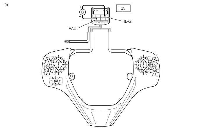
4.167,0.167 4.667,0.417 0.5,0.25 3.74,0.594 4.365,0.75 true 2.781,1.01 3.469,0.698 true 4.438,0.677 4.813,0.875 0.375,0.198 10 false IL+2 2.458,0.938 2.833,1.135 0.375,0.198 10 false EAU 0.156,0.083 0.354,0.292 0.198,0.208 10 false *a 4.344,0.208 4.719,0.406 0.375,0.198 10 false z9
*a Component without harness connected
(Steering Pad Switch Assembly)
- -


i.

Connect a positive (+) lead from the battery to terminal z9-5 (IL+2) and a negative (-) lead to terminal z9-8 (EAU) of the steering pad switch assembly connector.


ii.

Check that the steering pad switch assembly illumination illuminates.

OK:

The steering pad switch assembly illumination illuminates.


HINT:

If the result is not as specified, replace the steering pad switch assembly.


Hide 84250A 3.INSPECT STEERING PAD SWITCH ASSEMBLY (Type C)

a.

Measure the resistance according to the value(s) in the table below.
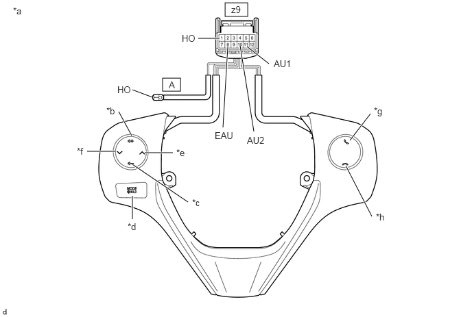
E362841C01
3.417,0.042 3.76,0.25 0.344,0.208 2.469,1.188 2.74,1.385 0.271,0.198 3.01,0.583 3.333,0.583 true 3.75,0.708 4.083,0.969 true 2.01,1.365 2.313,1.479 false 3.458,0.708 3.385,1.938 true 3.646,0.698 3.854,2 true 5.313,2.135 5.625,1.729 true 5.646,3.292 5.25,2.521 true 2,2.063 1.802,1.698 true 1.75,2.302 1.323,2.302 true 2.625,2.323 2.198,2.323 true 2.854,3.073 2.01,2.5 true 2.01,3.333 2.01,2.979 true 0.198,0.083 0.469,0.344 0.271,0.26 10 false *a 1.615,1.604 1.927,1.76 0.313,0.156 10 false *b 2.917,3 3.146,3.188 0.229,0.188 10 false *c 1.938,3.365 2.198,3.583 0.26,0.219 10 false *d 2.677,2.24 2.917,2.417 0.24,0.177 10 false *e 1.167,2.219 1.479,2.375 0.313,0.156 10 false *f 5.677,1.604 5.927,1.813 0.25,0.208 10 false *g 5.708,3.219 5.958,3.448 0.25,0.229 10 false *h 3.51,0.063 3.719,0.25 0.208,0.188 10 false z9 2.76,0.5 3,0.677 0.24,0.177 10 false HO 4.156,0.885 4.521,1.073 0.365,0.188 10 false AU1 2.563,1.208 2.75,1.406 0.188,0.198 10 false A 1.781,1.281 2.021,1.458 0.24,0.177 10 false HO 3.26,1.979 3.625,2.167 0.365,0.188 10 false EAU 3.75,2.052 4.115,2.24 0.365,0.188 10 false AU2
*a Component without harness connected
(Steering Pad Switch Assembly)
*b Volume+
*c Volume- *d MODE
*e Seek+ *f Seek-
*g Off Hook *h On Hook


Standard Resistance:
Tester Connection Condition Specified Condition
z9-1 (HO) - A-1 (HO) Always Below 2.5 Ω
z9-11 (AU1) - z9-8 (EAU) No switch pushed 95 to 105 kΩ
Seek+ switch pushed Below 2.5 Ω
Seek- switch pushed 313 to 345 Ω
Volume+ switch pushed 950 to 1050 Ω
Volume- switch pushed 2955 to 3265 Ω
z9-10 (AU2) - z9-8 (EAU) No switch pushed 95 to 105 kΩ
MODE switch pushed Below 2.5 Ω
On hook switch pushed 313 to 345 Ω
Off hook switch pushed 950 to 1050 Ω


HINT:

If the result is not as specified, replace the steering pad switch assembly.


b.

Check the illumination.

E362842C02
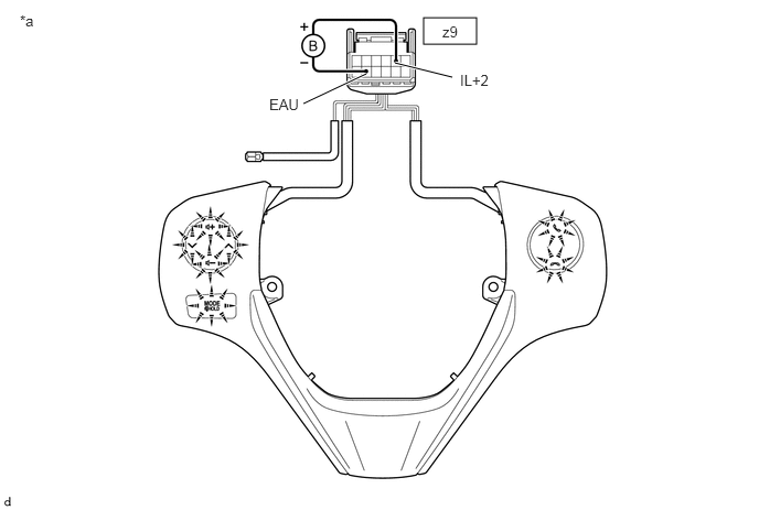
4,0.167 4.5,0.417 0.5,0.25 3.729,0.594 4.271,0.729 true 2.865,0.979 3.458,0.698 true 4.344,0.677 4.729,0.875 0.385,0.198 10 false IL+2 2.542,0.906 2.927,1.104 0.385,0.198 10 false EAU 0.188,0.115 0.438,0.302 0.25,0.188 10 false *a 4.177,0.219 4.563,0.417 0.385,0.198 10 false z9
*a Component without harness connected
(Steering Pad Switch Assembly)
- -


i.

Connect a positive (+) lead from the battery to terminal z9-5 (IL+2) and a negative (-) lead to terminal z9-8 (EAU) of the steering pad switch assembly connector.


ii.

Check that the steering pad switch assembly illumination illuminates.

OK:

The steering pad switch assembly illumination illuminates.


HINT:

If the result is not as specified, replace the steering pad switch assembly.