BM36W0E
_01
Vehicle Exterior
_088118
BODY DIMENSIONS
_0449217
ENGINE COMPARTMENT(for 3 Door)
F
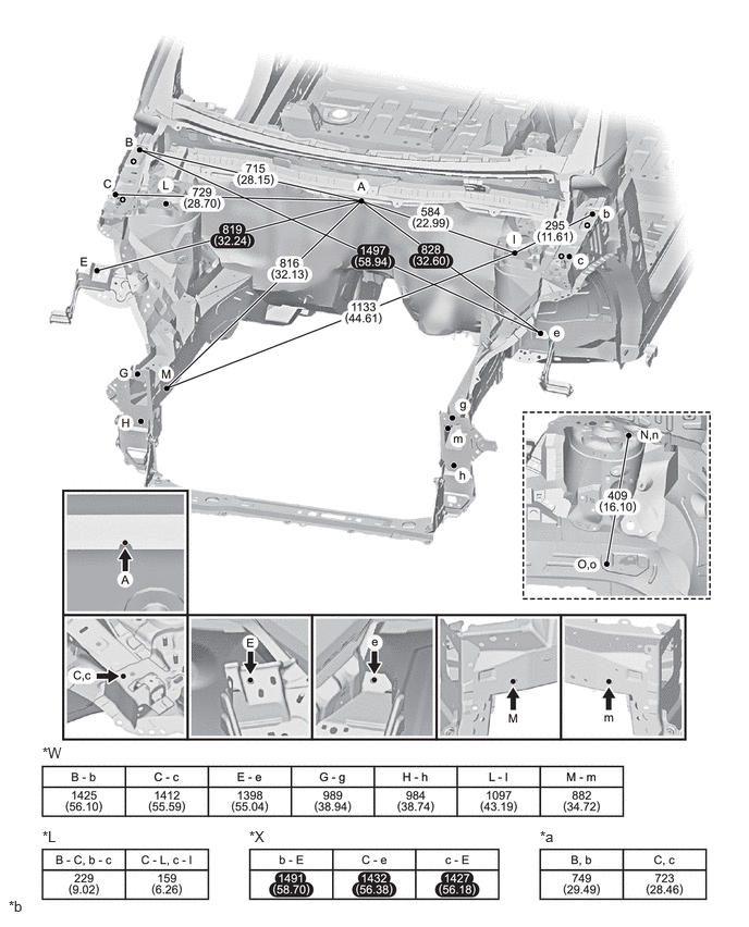
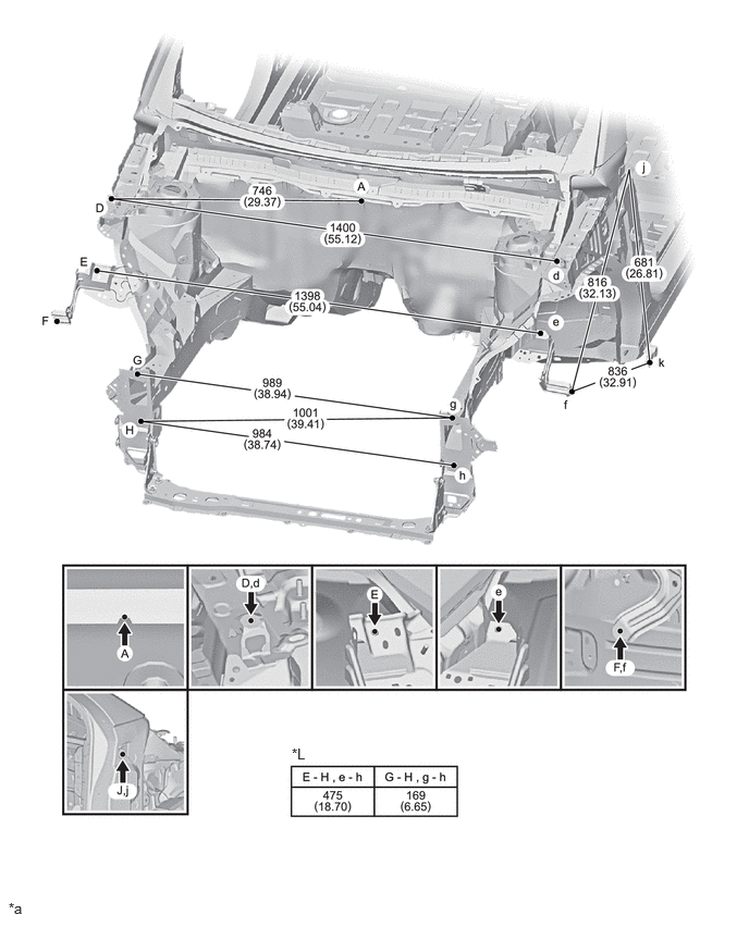
BODY DIMENSIONS ENGINE COMPARTMENT(for 3 Door) POINT-TO-POINT DISTANCE
- HINT:
- ·
Point E, e on the vehicle are asymmetrical.
·In cases in which only one dimension is given, left and right are symmetrical.
·For symbols, capital letters indicate right side of vehicle, small letters indicate left side of vehicle (seen from rear).
| Symbol | Name | Hole Diameter
mm (in.) |
|---|---|---|
| A | Cowl Upper Panel Center Mark | - |
| B, b | Hood Hinge Installation Nut | M8 (0.31) |
| C, c | Front Apron To Cowl Side Member Lower Standard Hole | φ10 (0.39) |
| D, d | Front Fender Installation Nut | M6 (0.24) |
| E, e | Front Fender Extension Standard Hole | φ10 (0.39) |
| F, f | Front Fender Installation Nut | M6 (0.24) |
| G, g | Crash Box Installation Nut | M10 (0.39) |
| H, h | Crash Box Installation Nut | M10 (0.39) |
| J, j | Front Fender Installation Nut | M6 (0.24) |
| K, k | Front Fender Installation Nut | M6 (0.24) |
| L, l | Fender Side Apron Standard Hole | φ8 (0.31) |
| M, m | Front Side Member Standard Hole | φ15 (0.59) |
| N, n | Front Spring Support Standard Hole | φ11 (0.43) |
| O, o | ABS Wire Harness Bracket Installation Nut | M6 (0.24) |

|
Symmetric distance | 
|
Asymmetric distance |
5.167,7.927 5.479,8.083
0.313,0.156
10
false
*a
0.083,8.594 0.396,8.75
0.313,0.156
10
false
*b
0.406,7.125 0.719,7.281
0.313,0.156
10
false
*W
0.406,7.927 0.719,8.083
0.313,0.156
10
false
*L
2.385,7.927 2.698,8.083
0.313,0.156
10
false
*X
| *a | Height from Imaginary Datum Line | *b | mm
(in.) |
| *W | Width distance | *L | Length distance |
| *X | Diagonal distance | - | - |
0.083,8.615 0.396,8.771
0.313,0.156
10
false
*a
2.792,7.135 3.104,7.292
0.313,0.156
10
false
*L
| *a | mm
(in.) |
- | - |
| *L | Length distance | - | - |