POWER DISTRIBUTION POWER INTEGRATION SYSTEM CONTROL POWER INTEGRATION CONTROL
FUNCTION OF MAIN COMPONENTS
|
*1: HV models *2: Models with mirror heater system *3: Models with manual air conditioning system *4: Models with LED type headlight *5: Models with halogen bulb type headlight *6: Models with front fog light (dealer option) |
||
| Components | Function | |
| Air Conditioning Amplifier Assembly | ·
Controls the air conditioning system. ·
Sends rear window defogger operation request signals to the main body ECU (multiplex network body ECU). |
|
| Main Body ECU (Multiplex Network Body ECU) | ·
Controls the body control systems. ·
Receives component operation requests and sends them to the semiconductor power integration ECU and power distribution box assembly. |
|
| Hybrid Vehicle Control ECU*1 | Sends the reverse signal to the power distribution box assembly. | |
| Rear Window Defogger Switch | Sends signals to the power distribution box assembly to operate the rear window defogger system and mirror heater system*2. | |
| Blower Motor with Fan Sub-assembly*3 | Blows according to the operation request signal. | |
| Semiconductor Power Integration ECU | ·
Receives signals from ECUs and switches, and then drives each component. ·
Shuts off current when a malfunction occurs. ·
Performs multiplex communication with the DLC3 and ECUs. |
|
| Power Distribution Box Assembly | ||
| Headlight ECU Assembly LH/RH*4 | ·
Controls the headlight system. ·
Receives operation request signals from the semiconductor power integration ECU and outputs illumination command signals to the headlights. |
|
| Headlight Assembly*5 | Low Bulb | Illuminates according to the operation request signal. |
| High Solenoid | Activates according to the operation request signal to control light distribution. | |
| Fog Light Assembly LH/RH*6 | Illuminates when the front light fog switch is turned on. | |
| Rear Window Defogger Wire | Generates heat when current is applied, warming the back door glass. | |
| Rear Combination Light Lens and Body | Taillight | Illuminates according to the operation request signal. |
| Rear Light Lens and Body | Rear Fog Light | Illuminates when the rear fog light switch is turned on. |
| Back-up Light | Illuminates when the shift position is in R. | |
| Outer Rear View Mirror Assembly LH/RH | Retraction/Restoration Motor | Retracts and restores the outer rear view mirror assembly according to the operation signal. |
| Mirror Heater*2 | Operates in conjunction with the rear window defogger, and generates heat when current is applied, warming the mirror surface. | |
| Occupant Detection Sensor | Sends the occupant detection signal for the front passenger seat to the power distribution box assembly. | |
| Front Seat Inner Belt Assembly LH | Sends the buckle switch signal for each seat belt to the power distribution box assembly. | |
| Rear Seat Inner Belt Assembly RH | ||
| Rear Seat Inner with Center Belt Assembly LH | ||
| IGP Relay | Turns the power supply to motive force generating loads on/off. | |
| Central Gateway ECU (Network Gateway ECU) | Relays the signal between the CAN communication lines. | |
| DLC3 | Connects to the GTS. | |
FUNCTION
| Components | Semiconductor Power Integration ECU | Power Distribution Box Assembly | Operation Signal Communication Support |
|---|---|---|---|
| Headlight ECU Assembly*1 | ○ | - | X |
| Headlight Assembly Low Bulb*2 | ○ | - | X |
| Headlight Assembly High Solenoid*2 | ○ | - | ○ |
| Fog Light Assembly*3 | ○ | - | ○ |
| Rear Window Defogger / Mirror Heater*4 | - | ○ | ○*5 / X*6 |
| Taillight | - | ○ | ○ |
| Rear Fog Light | - | ○ | ○ |
| Back-up Light | - | ○ | X |
| Outer Rear View Mirror Assembly | - | ○ | ○ |
| Panel Illumination | - | ○ | ○ |
| Blower Motor with Fan Sub-assembly*6 | - | ○ | X |
| Passenger Seat Buckle Switch Delegated Input | - | ○ | - |
| Occupant Detection Sensor Delegated Input | - | ○ | - |
| Rear Seat RH Buckle Switch Delegated Input | - | ○ | - |
| Rear Seat CTR Buckle Switch Delegated Input | - | ○ | - |
| Rear Seat LH Buckle Switch Delegated Input | - | ○ | - |
| IGR Relay*7 | - | ○ | X |
- HINT:
-
○: Supported
-
X: Not supported
-
*1: Models with LED type headlight
-
*2: Models with halogen bulb type headlight
-
*3: Models with front fog light (dealer option)
-
*4: Models with mirror heater system
-
*5: Models with automatic air conditioning system
-
*6: Models with manual air conditioning system
-
*7: Built into power distribution box assembly
Component Operation Output Function
This function turns the corresponding component on and off in accordance with operation signals or switch input signals from the ECU.
Semiconductor Fuse Function
When an abnormal electric current occurs during operation of components, the components are turned off by shutting off the current before electrical wire emits smoke.
The electrical current is maintained shut off while operation signals or switch signals are on.
When operation signals or switch signals are turned off, the shut off condition is canceled.
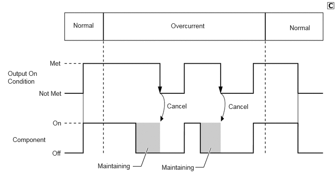
Delegated Input/Output Function
Signals are received from the various sensors and switches, and sent to the various ECUs via multiplex communication line (CXPI communication line).
Scene-based Power Supply Control
When an emergency shutdown while driving is performed, the IGR relay is held in the ON condition. For details, refer to the Electric Power Control.
Power Supply Management Control
When vehicle is stopped:
When the battery SoC has decreased, notification is sent to the driver via the multi-information display, etc. (Models with smart entry and start system)
When vehicle is being driven:
When the battery SoC has decreased, supply of power to some systems is stopped to reduce load.
Diagnosis Communication
Checking Diagnostic Trouble Codes (DTCs) regarding ECU and other malfunctions is possible by connecting the GTS.
The semiconductor fuse condition (shut off or not) can be confirmed by connecting the GTS.
Reprogramming
Reprogramming can be performed by connecting the GTS.
- HINT:
-
Refer to the Repair Manual for the details of the diagnostic communication and reprogramming.
DIAGNOSIS
In order to make system inspections easier to perform, a diagnosis function is used in consideration of serviceability. The Diagnostic Trouble Codes (DTCs) of malfunctions can be read by connecting the GTS. For details, refer to the Repair Manual.