M15A-FKS ENGINE CONTROL SFI SYSTEM DETAILS THROTTLE POSITION SENSOR
CONSTRUCTION
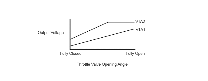
A non-contact type throttle position sensor is used. The sensor uses a Hall IC*1, which can retrieve the strength of the magnetic field as an electrical signal using Hall effect*2, in which the output voltage can be directly received in accordance with the throttle valve opening angle. When the throttle valve opening angle changes, the angle of the magnetic field with respect to the direction of the flow of current in the Hall IC changes. As a result, the strength of the potential difference created by the Hall effect varies and is sent to the ECM as a throttle valve opening angle signal. Also, duplicate sensors (main and sub) with differing sensor output characteristics, are used, ensuring reliability.
- HINT:
-
*1: An electrical component which uses the electromotive force resulting from the potential difference in the magnetic field.
-
*2: Phenomenon in which a potential difference is generated perpendicular to the flow of current through a conductor or semiconductor within a magnetic field not parallel to the flow of current.