M15A-FKS ENGINE MECHANICAL ENGINE UNIT DETAILS CYLINDER HEAD
CONSTRUCTION
The cylinder head structure is simplified by separating the cam journal portion (camshaft housing sub-assembly) from the cylinder head sub-assembly.
The cylinder head sub-assembly, which is made of aluminum, contains pentroof-type combustion chambers. The spark plug is located in the center of the combustion chamber in order to improve the engine's anti-knock performance.
The shape of the intake ports, the combustion chambers and the injector fuel spray pattern have been optimized to enhance combustion efficiency.
By incorporating the exhaust port into the cylinder head sub-assembly, the exhaust port length has been optimized while also achieving exhaust gas cooling performance to improve fuel economy and exhaust performance.
A laser cladded valve seat is used, thus enabling the shape of the intake port to be optimized, increasing the tumble flow and intake air flow volume, improving engine power and fuel economy.
The valve lash adjuster assemblies are installed in the upper part of the cylinder head sub-assembly, creating a structure where the oil passage supplying oil to the valve lash adjuster assemblies are combined with the interior of the cylinder head sub-assembly.
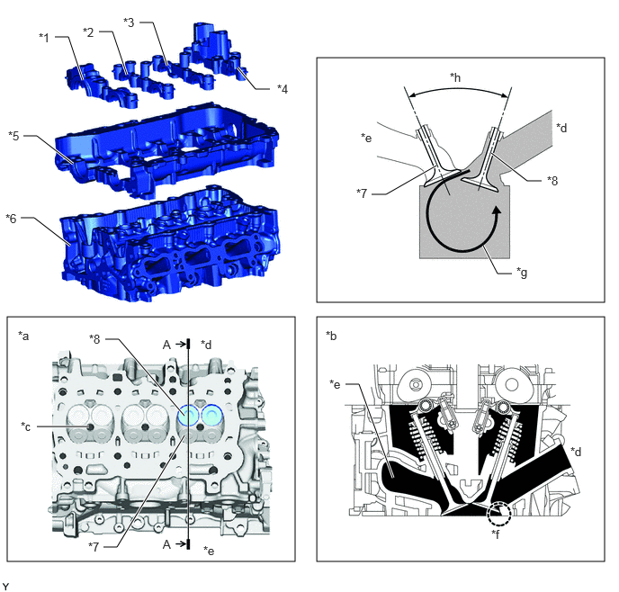
| *1 | No. 1 Camshaft Bearing Cap | *2 | No. 2 Camshaft Bearing Cap |
| *3 | No. 3 Camshaft Bearing Cap | *4 | No. 4 Camshaft Bearing Cap |
| *5 | Camshaft Housing Sub-assembly | *6 | Cylinder Head Sub-assembly |
| *7 | Exhaust Valve | *8 | Intake Valve |
| *a | View from Bottom Side | *b | A-A Cross Section |
| *c | Spark Plug Hole | *d | Intake Side |
| *e | Exhaust Side | *f | Laser Cladded Valve Seat |
| *g | Tumble Flow | *h | 41° |
The exhaust ports of each cylinder have a structure that positions them inside the cylinder head and delivers the exhaust gas into the exhaust manifold, achieving improved exhaust performance and engine output performance. Also, by optimizing the length and diameter of the exhaust port and by cooling the exhaust gas using the water jackets built into the cylinder head sub-assembly, engine performance and exhaust cooling performance have been enhanced.
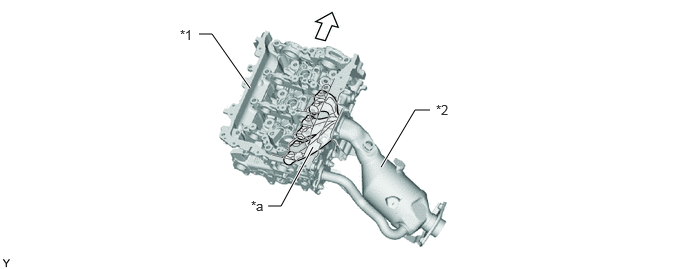
| *1 | Cylinder Head Sub-assembly | *2 | Exhaust Manifold |
| *a | Exhaust Port | - | - |

|
Engine Front | - | - |
A 2 part water jacket is used to optimize coolant volume and coolant flow speed, realizing high cooling performance.
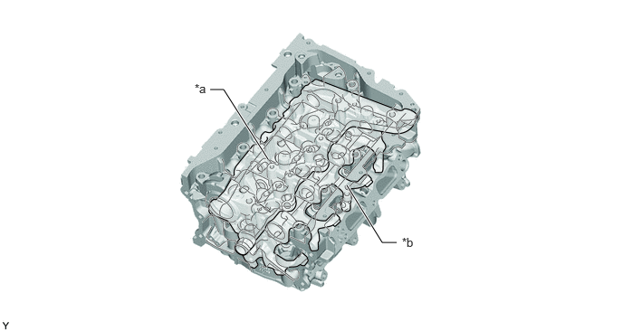
| *a | Water Jacket (Upper Side) | *b | Water Jacket (Lower Side) |