M15A-FKS ENGINE MECHANICAL ENGINE UNIT DETAILS BALANCE SHAFT
CONSTRUCTION
An engine balancer assembly is used to counteract the rotational moment that may cause increased vibration and noise, reducing vibration and noise (reducing muffled sounds from the vehicle).
The crankshaft directly drives the No. 1 balance shaft.
In addition, a resin gear is used on the driven side to suppress noise.
The engine balancer assembly is separated from the stiffening crankcase assembly, making it easier to be serviced.
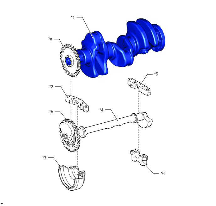
| *1 | Crankshaft | *2 | No. 2 Balance Shaft Housing |
| *3 | No. 1 Balance Shaft Housing | *4 | No. 1 Balance Shaft Sub-assembly |
| *5 | No. 4 Balance Shaft Housing | *6 | No. 3 Balance Shaft Housing |
| *a | Balance Shaft Drive Gear | *b | No. 1 Balance Shaft Driven Gear (Resin Gear) |
Combustion is performed at every 120° crank angle in an in-line 3-cylinder engine, creating the primary pitching moment in the crankshaft and causing vibration. In order to counteract half of the vibration, a counterweight based on half of the reciprocating mass is positioned on the crankshaft. This leaves a rotational moment at half the reciprocating mass in the same direction in which the crank is rotating, resulting in increased vibration and noise.
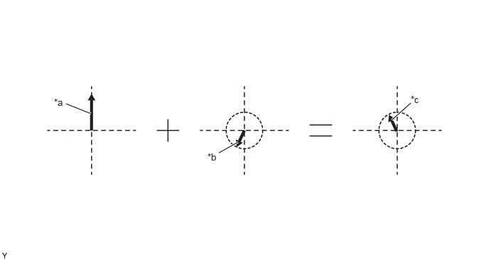
| *a | Primary Pitch Moment Caused by Combustion | *b | Primary Pitch Moment Caused by Counterweight |
| *c | Rotational Moment | - | - |
In order to counteract the rotational moment, the No. 1 balance shaft sub-assembly is made to rotate at the same speed as the crankshaft to create the same moment in the opposite direction, offsetting the vibration.
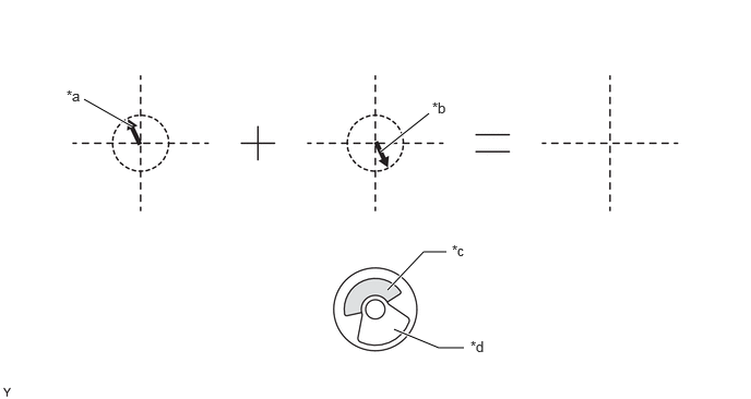
| *a | Rotational Moment | *b | Moment Caused by Balance Shaft |
| *c | Balance Shaft Mass (Engine Rear Side) | *d | Balance Shaft Mass (Engine Front Side) |