STEERING COLUMN STEERING COLUMN SYSTEM DETAILS MANUAL TILT AND TELESCOPIC MECHANISM
CONSTRUCTION
The manual tilt and telescopic mechanism allows adjustment of the steering wheel assembly position in the vertical and longitudinal (extending and retracting) directions through lever operation. This provides a comfortable driving position for the driver.
The tilt adjustment range is 40 mm (1.57 in.) and the telescopic adjustment range is 50 mm (1.97 in.).
When the tilt and telescopic mechanism is in its locked state, the tilt and telescopic lever at the lock position causes the cam of the tilt and telescopic lever bolt to tighten the tilt and telescopic bracket. This secures the upper bracket, tilt and telescopic bracket and lower housing, so movement in the tilt direction and in the telescopic direction is locked.
When the tilt and telescopic mechanism is in its free state, the tilt and telescopic lever at the free position causes the cam of the tilt and telescopic lever bolt to loosen the tilt and telescopic bracket. This frees the upper tube and the lower housing to move in the tilt direction and in the telescopic direction, enabling adjustment.
The tilt and telescopic mechanism mainly consists of a tilt and telescopic bracket, upper tube, lower housing, cam, tilt and telescopic lever bolt and tilt and telescopic lever.
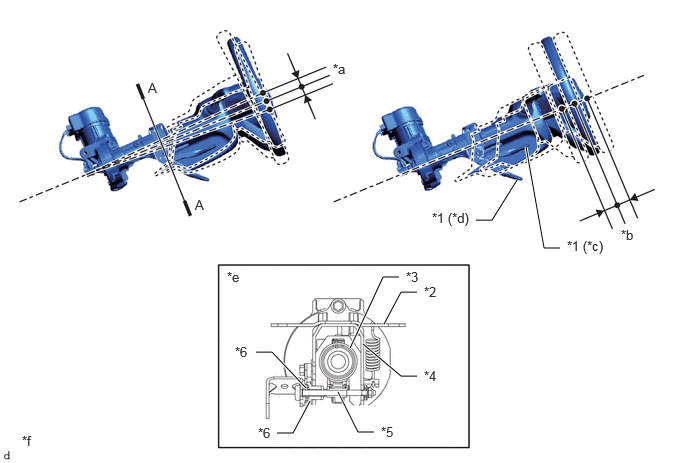
| *1 | Tilt and Telescopic Lever | *2 | Upper Bracket |
| *3 | Upper Tube | *4 | Tilt and Telescopic Bracket |
| *5 | Tilt and Telescopic Lever Bolt | *6 | Cam |
| *a | Tilt Stroke 40 mm (1.57 in.) | *b | Telescopic Stroke 50 mm (1.97 in.) |
| *c | Lock Position | *d | Free Position |
| *e | A-A Cross Section | *f | The illustrations shown are examples only. |