STEERING COLUMN STEERING COLUMN SYSTEM DETAILS ENERGY ABSORBING MECHANISM
CONSTRUCTION
The No. 2 steering intermediate shaft assembly and electric power steering column sub-assembly each contain an energy absorbing mechanism.
OPERATION
Primary Collision
The No. 2 steering intermediate shaft assembly contracts during a primary collision (vehicle to another object) to reduce the possibility of the electric power steering column sub-assembly and the steering wheel assembly protruding further into the cabin.
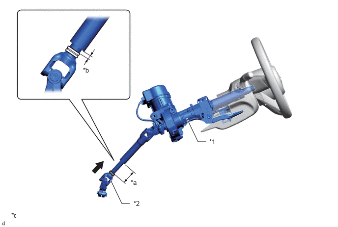
| *1 | Electric Power Steering Column Sub-assembly | *2 | No. 2 Steering Intermediate Shaft Assembly |
| *a | Before Collision | *b | After Collision |
| *c | The illustrations shown are examples only. | - | - |

|
Collision | - | - |
Secondary Collision
The electric power steering column sub-assembly contracts during a secondary collision (driver and steering wheel assembly) in order to absorb impact. During a collision, the breakaway pin which connects the telescopic hook lock and lower housing shears and the upper tube and steering wheel assembly move forward. At this time, the sliding friction between the upper tube and lower housing helps to absorb the energy of the collision.
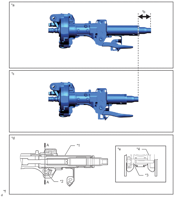
| *1 | Upper Tube | *2 | Telescopic Hook Lock |
| *3 | Breakaway Pin | *4 | Lower Housing |
| *a | Before Collision | *b | Sliding Stroke |
| *c | After Collision | *d | Upper Tube and Lower Housing Cross Section |
| *e | A-A Cross Section | *f | The illustrations shown are examples only. |